I have been working hard at the 2nd revision of the Gemini 3D printer prototype. The new version has a sturdier frame assembly which is easier to put together and more straight forward in it’s construction. This is a work-in-progress of the new design:
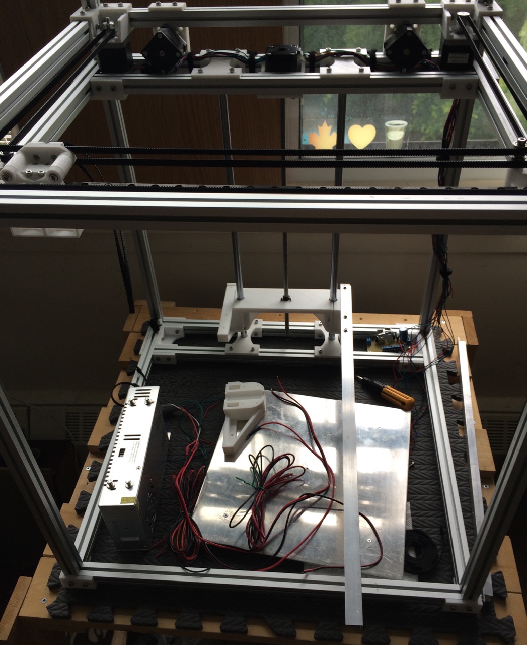
The Z axis has now been re-designed as a cantilever style platform which eliminates the binding and levelling issues found with the first prototype that used a dual drive configuration. This platform eliminates two 12mm smooth rods and one Z motor from the build as well.
This new Z portion is still under testing but so far looks like it should do the trick. I am considering changing it to use all four smooth rods if the completed assembly ends up having issues with keeping the platform level on just the two rods.
In progress as I write this is a set of parts for mounting the 24v power supply to the frame. Not pictured are two panels for the rear of the printer which will hold 120mm fans for cooling the electronics. All motors are now mounted at the top-rear of the printer and the extruder motors are located beside the gantry drive motors.
There will be enclosing panels which will protect the electronics and create a pair of airflow channels from the 120mm fans which will cool the motors, PSU and stepper drivers and exhaust out of the top of the machine away from the print area.
There are a few small details to work out for mounting the end-stop microswitches for all three axis as well as attaching the voltage conversion and Smoothieboard to the frame at the back. Once those parts are designed and then printed I will be doing a rebuild of the above photographed assembly.
The Z motor mount needs to be flipped to allow for clearance of the heads of the mounting bolts and gain a few more millimetres of print height.
For mounting the panelling there will be small snap-fit parts that will form mounting points – the idea is to use some double-sided tape to hold the clip-on parts in place.
Once the final assembly is built-up the final parts to be designed will be the hotend mounts and a new filament pusher design. I hope to have all of that completed within the next week and then start running some test prints in late June to see how this all works out.
One final set of changes involving the electronics will be done in July – there are two 120mm fans, one 40mm fan and a 50mm blower fan that currently I am running with a 12v voltage converter because I only had 12v models of these fans. I have placed an order for these four fans in 24v models, once they have arrived I will upgrade the fans from the test build and bypass the 12v converter circuit that drives them. The LM7812 on the converter board will be replaced with a LM7805 to produce 5v from the PSU and that will power the Smoothie board itself, allowing the machine to be fully self-contained and not powered from USB.
One final consideration is what the user-interface will be like on the machine itself. Running a full-LCD display such as the RepRapDiscount Graphic Controller was the original concept, however I am also considering connecting an Arduino nano to the Smoothieboard to drive a different LCD display as well as serve as a secondary watchdog for internal temperatures.
For initial testing the machine will be accessible via the network as well as USB for direct control.
Recent Comments