Using OpenSCAD to recreate – and hopefully finally finish – the X-Carriage design has been proving beneficial.
It’s now much easier to programatically place the parts in a mockup of the assemblies and see how they’ll fit – and most importantly, I can make parametric adjustments to the placing and have the design automatically reshape itself to match.
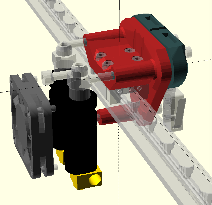
As you will see in the above rendered view of the X-Carriage, it’s starting to get pretty busy with components.
The goal here is to get everything to fit in as small a space as possible but still end up with printable parts.
What this partly entails is that components cannot be so close together that the ensuing printed part has thin walls or impossible overhangs
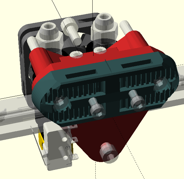
The belt clamp shown below is already pretty detailed with small design elements, these can be tricky for a 3D printer, so I’ve had to do some test prints to verify it is actually printable (which it is.)
– There are still several mounting bolts not included within the rendered design and modules need to be written for rendering metric nuts and carving out insertion points for them.
– A 50mm blower fan needs to be somehow squeezed into this assembly as well, in order for the printer to also support print cooling for plastics like PLA.
– A more accurate (and parametric) version of the pneumatic pushfit connector needs to be drawn to give a better concept of the size and shape of the part.
– As described in my previous post regarding the X and Y axis end-stops, the X end-stop is shown in it’s approximate new location, the parts will need to be extended to have mount points for this switch.
I have plenty of ideas for how the cover for this assembly can be made, however they may change once all the hardware is accommodated for and the resulting shape can be determined.
Recent Comments