After getting the latest prototype of the Gemini 3D printer up and running I was dissatisfied with the assembly, implementation, appearance and performance of the overall system.
I starting playing around with some ideas in Sketchup by moving bits around and fiddling with the layouts and came to realize that I could eliminate several of the aluminum extrusions and reduce the overall materials cost as well as exterior size of the machine.
A few new parts came together really fast once I started reimagining the overall frame design
- New corner bracing – the first design did not work well, the second design worked better but turned out to not have the requisite strength or aesthetics I would have hoped for. Assembly was a chore to deal with if parts needed to be changed out. The new corner braces are a more traditional style but have been 3D printed in ABS with thick perimeters to make them strong and less brittle.
- From the new corner brace design I created a new 120mm fan mount with the AC plug and switch integrated as with the last prototype – however the part now forms a protective box around the live AC wiring and I have designed a fan duct to redirect the air vertically into a channel which will cover the power supply and direct the air towards the left corexy drive motor and extruder motor.
- With the new compact frame design I needed to come up with a new way of mounting the vertical smooth rods for the Z axis – I came up with a snap-fit connector which uses and M4 bolt to clamp the rod in place. By using these clamps I will be able to ensure correct and sturdy alignment of the linear axis is something that is easy to achieve. Disassembly and servicing the axis will be greatly simplified with these parts.
The new clamping system also permits the effector to move towards the back of the printer by over 20mm more than it could previously – this allows me to move the bed that much closer to the linear rails which reduces the lever/fulcrum effect of the moving platform. - Some basic repositioning of the effector parts is also necessary – the flat aluminum stock which I used for the Rev 3 prototype is not stiff enough to prevent the X axis linear rail from sagging towards the centre which causes uneven contact with the bed across the width of the print area. I will be replacing this assembly with the one from the previous build where the linear rail was attached to a 3 sided aluminum channel, or potentially an L shaped channel for more rigidity.
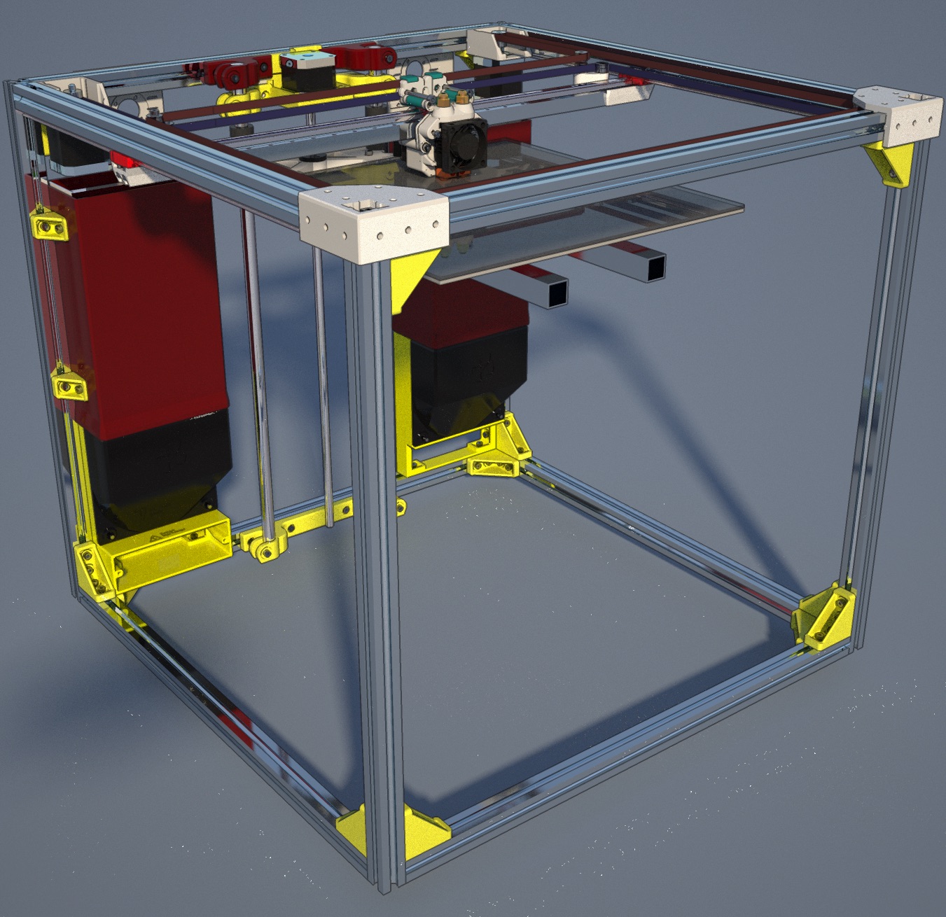
In the rendering shown above, all of the non-white and non-green plastic components are part of the revised configuration.
The overall CoreXY component of the current build is satisfactory and thus will be pretty much remaining the same, aside from the modified X axis support and some cosmetic revisions to the printed components.
Recent Comments