As I’ve discussed in my last couple of posts, I am redesigning the Z-Axis for the Gemini prototype.
The 12mm rods are now doubled up on each side and I am working on a test assembly which uses single LM12UU bearing per rod. From an ideal perspective, I should probably double up the bearings on the frontmost rod for each side.
Instead I am working on a test assembly which uses only one per side in order to make the mechanism shorter and optimize the achievable Z height for the printer.
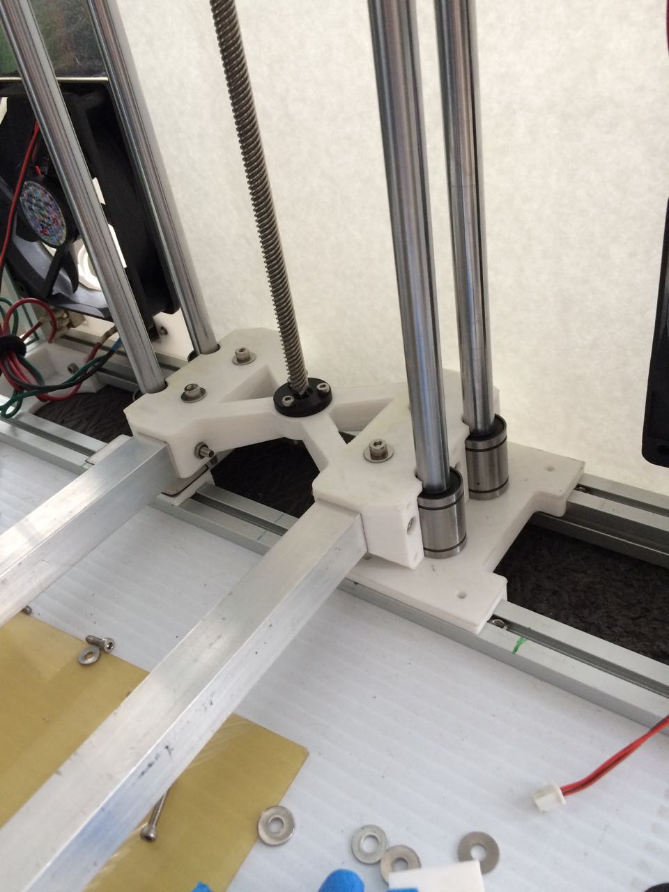
The above part was designed in OpenSCAD. The new build platform support arms are 3/4″ square aluminum tubes which have been drilled and bolted into the printed part using five M4x40 bolts per arm. There is no possibility of flex in either the arms or their bolt mount pattern of three across and two vertical.
Clamping blocks will be 3D printed and bolted onto each side using six M3x20 bolts per side.
Including the three M3x20 bolts which secure the leadscrew bushing to the part there are fifteen M3x20 bolts and ten M4x40 bolts required to hold everything together into a nice compact assembly.
Once I have the clamp parts designed, printed and attached, I can get the rod holders bolted down into their proper alignment and start testing the design for any sign of flex or binding when being driven by the motor. If all goes well then I will start on the design of the build platform mounts – they will be 3D printed and bolted to the support arms.
One thing to note is that with the above pictured reduced-height assembly design is that the leadscrew is not inside the bushing at it’s lowest position. If the assembly works as I hope then I can simply flip the Z motor mount upside down and re-mount the motor lower into the frame.
Recent Comments