by B Cantin | Jun 21, 2015 | Gemini 3D Printer
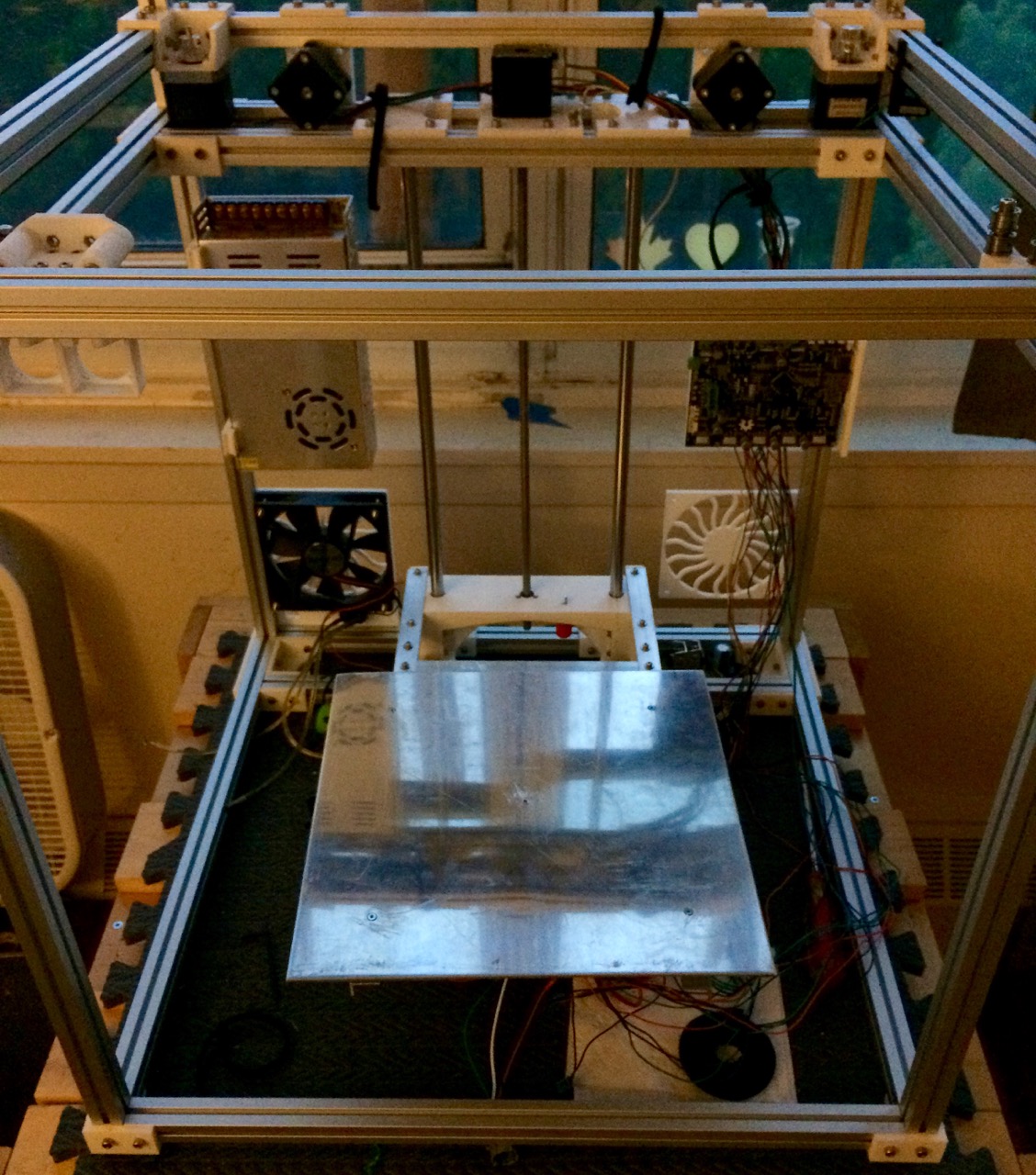
The latest test build of the second revision of the Gemini 3D printer is coming along well. Shown in this photo (sorry for the bad lighting) is the mounting of the fans (only one shown) along with the 24v power supply, motors and of course the Smoothieboard.
The print bed is not actually mount yet in this photo, it’s merely resting on the Z axis platform to ensure the design of the assembly is capable of supporting it’s weight – which it is.
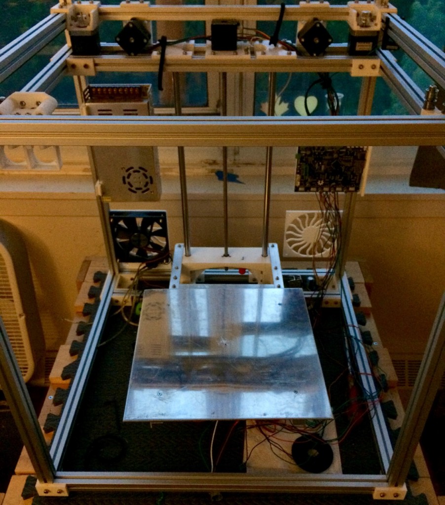
One addition to note is the inclusion of the Z axis endstop switch at the top of the machine, beside the Z axis drive motor and the spring loaded adjustment screw on the moving platform. This will allow for easy fine-tuning of the print bed height.
I am looking at revising the parts that hold the Z axis smooth rods – there is a slight bit of wiggle room with the current design which has had the unintended result of causing some misalignment of the two 12mm rods. The result of this is that the platform is skewed at a slight angle. Additionally, getting the smooth rods in proper alignment with the drive motor is trickier than I would like.
I am looking into creating a single central part at the top of the Z axis with which to mount the Z motor, endstop and rods with side-clamping of the rods which should provide precise mounting of the rods.
There are a few more parts that need to be designed for mounting of the front power switch as well, so the next build picture have an improved and simpler to assemble Z axis, better wiring management and power controls.
Stay tuned for later this week!
by B Cantin | Jun 16, 2015 | Gemini 3D Printer
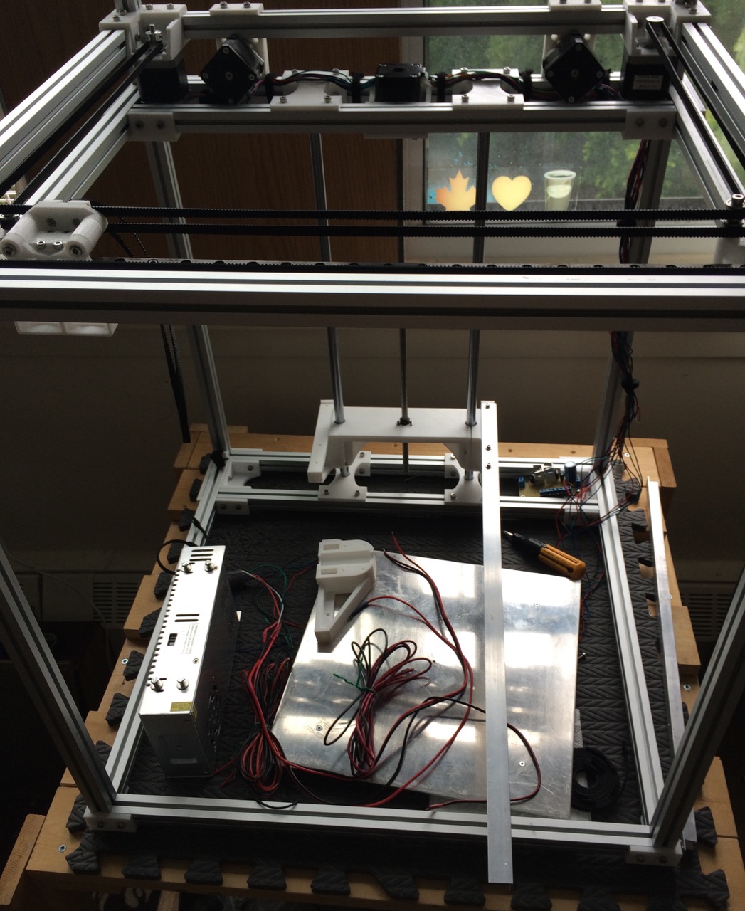
I have been working hard at the 2nd revision of the Gemini 3D printer prototype. The new version has a sturdier frame assembly which is easier to put together and more straight forward in it’s construction. This is a work-in-progress of the new design:
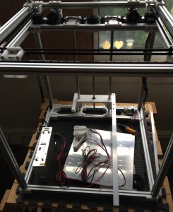
The Z axis has now been re-designed as a cantilever style platform which eliminates the binding and levelling issues found with the first prototype that used a dual drive configuration. This platform eliminates two 12mm smooth rods and one Z motor from the build as well.
This new Z portion is still under testing but so far looks like it should do the trick. I am considering changing it to use all four smooth rods if the completed assembly ends up having issues with keeping the platform level on just the two rods.
In progress as I write this is a set of parts for mounting the 24v power supply to the frame. Not pictured are two panels for the rear of the printer which will hold 120mm fans for cooling the electronics. All motors are now mounted at the top-rear of the printer and the extruder motors are located beside the gantry drive motors.
There will be enclosing panels which will protect the electronics and create a pair of airflow channels from the 120mm fans which will cool the motors, PSU and stepper drivers and exhaust out of the top of the machine away from the print area.
There are a few small details to work out for mounting the end-stop microswitches for all three axis as well as attaching the voltage conversion and Smoothieboard to the frame at the back. Once those parts are designed and then printed I will be doing a rebuild of the above photographed assembly.
The Z motor mount needs to be flipped to allow for clearance of the heads of the mounting bolts and gain a few more millimetres of print height.
For mounting the panelling there will be small snap-fit parts that will form mounting points – the idea is to use some double-sided tape to hold the clip-on parts in place.
Once the final assembly is built-up the final parts to be designed will be the hotend mounts and a new filament pusher design. I hope to have all of that completed within the next week and then start running some test prints in late June to see how this all works out.
One final set of changes involving the electronics will be done in July – there are two 120mm fans, one 40mm fan and a 50mm blower fan that currently I am running with a 12v voltage converter because I only had 12v models of these fans. I have placed an order for these four fans in 24v models, once they have arrived I will upgrade the fans from the test build and bypass the 12v converter circuit that drives them. The LM7812 on the converter board will be replaced with a LM7805 to produce 5v from the PSU and that will power the Smoothie board itself, allowing the machine to be fully self-contained and not powered from USB.
One final consideration is what the user-interface will be like on the machine itself. Running a full-LCD display such as the RepRapDiscount Graphic Controller was the original concept, however I am also considering connecting an Arduino nano to the Smoothieboard to drive a different LCD display as well as serve as a secondary watchdog for internal temperatures.
For initial testing the machine will be accessible via the network as well as USB for direct control.
by B Cantin | May 30, 2015 | Gemini 3D Printer
As per my posts over the previous days, there is a new gantry in the works for the Gemini 3D printer.
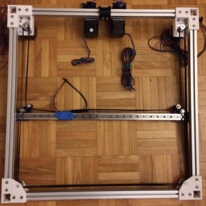
Last night the motor mounts were printed and attached to the frame. These have a lot more strength than the previous version and have slotted holes for the for M3 bolts that attach the NEMA17 stepper motors. This will allow for tensioning the belt once it’s clamped to the x-carriage, which is the next part that will be designed and printed.
Since the photo was taken I have also printed a revision of the X-end/y-carriage mounting part which corrects the belt alignment and allows for adjustment of the x-axis – I will detail that assembly in another post.
Note that the belt path is not correct in relation to the x-carriage in this photo, it will run straight like it should once the part with the belt clamps is assembled.
by B Cantin | May 29, 2015 | Gemini 3D Printer
Things are progressing fairly well with the second revision of the Gemini 3D printer’s CoreXY gantry. The new corner pieces assembled well the first time and the resultant frame is quite strong and rigid.
The former corner bracing scheme was fraught with issues of warping and it was a chore to get things completely square – this is not an issue with the new design.
A large part of why this is working is a twofold change with how the parts are designed – I have increased the thickness from 3mm to 5mm and added 1mm thick guide ridges that fit into the slots of the aluminum extrusion frame.
No photos for this post, but I should have an update later today – the motor mounts are being printed off as I write this. These new motor mounts should be much tougher than the previous ones which I anticipate should eliminate the warping issues found in the original prototype.
Getting the object models to be manifold from Sketchup turned out to be a problem, however Netfabb’s mesh repair made short work of correcting the issue. Potentially I could have spent a lot of time trying to fix up the models in Sketchup, but due to the complexity of some of the details on the part it seemed to be a fools-errand. Some things are just out of the STL export plugin’s realm of capabilities and these parts fall into that category.
The new motor mounts will bolt to the frame on two inner faces as well as the lower side of the rear span. This might be a bit of over-designing on my part, but I wanted to ensure that there was little chance for the mounts to come loose from vibrations and heat.
A small revision is necessary for the X axis configuration. I need to re-introduce the previous design’s slotted mounting system for the support beam.
The reason for this is that although the design is very accurate, the reality of mounting the parts to the linear carriages is that there is a small amount of wiggle room required to get things squared away nicely.
Currently the assembly is off by a fraction of a millimetre which prevents it from sitting perfectly even between the two sides of the frame. The result of that is excessive pressure on the Y carriages causing them to come out of alignment. This should be a fairly easy fix by slotting the four-point mounting holes on the aluminum flat bar and slotting the rail mount holes on the X-ends.
by B Cantin | May 28, 2015 | Gemini 3D Printer
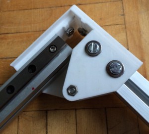
As part of the redesign and strengthening of the Gemini 3D, working towards a more production-like model instead of the flimsy proof-of-concept prototype I have printed and assembled one of the new top idler corners.
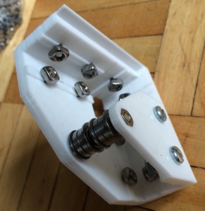
This is made as a two piece assembly in order to keep the part strong along the print layering. The gantry itself will form a box frame which will then be lowered onto the four vertical corner posts of the frame.
Initial testing is indicating that this corner is a snug fit and very strong. The idlers align well with the idlers on the new flat-bar X axis, so everything is coming together nicely for the new design.
Below is the corner with it’s two extrusions inserted.
by B Cantin | May 27, 2015 | Gemini 3D Printer
As I mentioned in my previous post, I am experimenting with a revised gantry for the Gemini 3D printer.
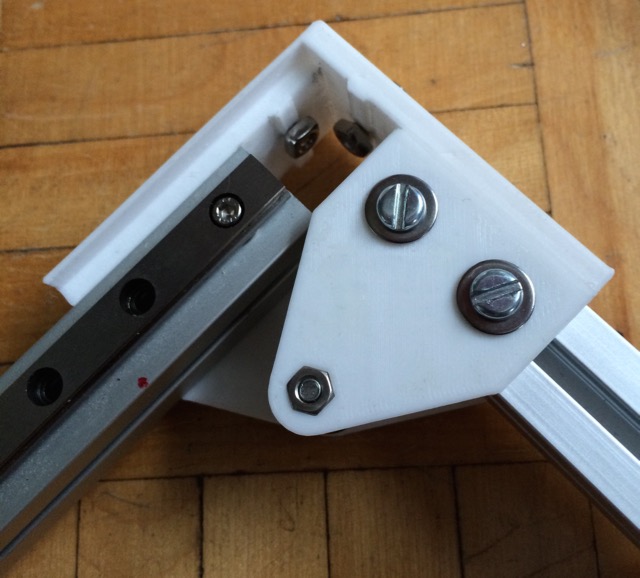
Here is a test assembly of the new idler ends assembled with the flat aluminum bar support and the 9mm hiwin rail for the X axis mounted.
This design is proving to be adequately stiff for the light weight x-carriage I have been working with on the prototype. Some simple testing shows that it would probably be stiff enough to carry a pair of stepper motors if the design was to use direct drive extruders, however in such a scenario I would probably want a stiffer assembly than the flat bar.
Since the Gemini uses dual bowden extruders, this is a moot point.

This assembly is actually quite simple – there are two printed plastic components, one on each end.
Each end holds three idlers and each idler is composed of two bearings.
The idlers are mounted on M4 bolts which have enough plastic support at their base to handle the tension of the GT2 belts once the gantry is fully assembled.
The lower idlers on the posts that have two idlers are there to prevent the timing belts from rubbing against the idler tower and carry no direct loading. In the initial prototype I observed some rubbing against the plastic support pieces and it occurred to me that the easiest way to solve this problem was to add an extra idler per side.
The double idlers are separated by a small M4 nut. The machining of the bolt head and nut are the perfect size to engage the inner ring of the bearings and not contact the rotating outer assembly and thus eliminate the need for washers.
It would take much more force than this machine will exert to bend the M4 bolts or crack the plastic end pieces.
Two M3 bolts on each side sandwich the 9mm rail and the flat bar to the plastic end piece, with an additional three M3 bolts securing the rail to the bar directly which are spaced evenly along it’s length.
This construction ensures that the bar and the rail the are aligned correctly and that they cannot flex independently which provides the necessary stiffness.
Four more M3 bolts on each end connect the X axis to the hiwin carriages on the Y axis with the flat bar sandwiched between the plastic and carriage. This gives additional stiffness to the assembly and ensures proper squared alignment on the Y rails.
by B Cantin | May 26, 2015 | Gemini 3D Printer
The previous prototype of the Gemini 3D printer gantry worked effectively however there are many aspects that I have been working on revising.
Plastic parts in use on the x-end/y-carriage were not designed to be robust in the prototypes – it was assumed that they would be replaced with a better design in the future, so they were made with the most minimal use of plastic to avoid waste on what was expected to be a throw-away part.
While working on what will be a more robust setup I’ve been experimenting with several conceptual changes.
The first major revision involves the belt paths. The motor-end idler pulleys are being removed entirely and the inner dimensions of the belt path will be significantly reduced by this change. This removes several bearings and an extra 90 degree turn from the belt path, shortening the length of GT2 timing belt required and lowering the part count.
The second major revision is to decouple the gantry from the top of the Z axis which will provide more space for the X carriage assembly as well as creating a more directly square frame to constrain the gantry within. I am working on a new design which places the Y axis linear rails underneath the aluminum extrusion instead of on top of it.
A potential pitfall of this change is that it may require an extra metre of aluminum extrusion, or some more drastic re-arrangement of the frame design to accomplish this.
The third major revision – which may be a bit more controversial than the previous two – is to replace the aluminum channel supporting the X axis with a thick length of aluminum flat bar. The reasoning for the channel is that having two different planes on the support will prevent deflection of the X axis over it’s widthwise span.
Testing has indicated that it takes one-thousand grams or more of weight to cause significant deflection of the hardened steel linear channel on it’s own. Bolting it to a length of flat bar increases the amount of weight necessary to cause deflection.
However, the current X carriage design weighs only 200 grams which is not enough to create any significant distortion.
I am still working on this design and might decide to play it safe and use a corner channel ultimately as this will also provide the necessary mounting points for the new design as well as the deflection strength.
Testing is still in progress for this – ultimately the extra reinforcement seems unnecessary if the x-carriage is a fifth of the weight that necessitates it.
The forth revision involves the belt alignment as it relates to the X axis. The goal here is to make the x-end/y-carriage assembly simpler and stronger as well as aligning the belts in such a way as to make clamping them to the X-carriage simpler. This revision puts all four ends of the two belts inline with each other, which is strangely not something I’ve seen elsewhere in a corexy design.
Additional changes to the frame, motor mounts and idlers are in the works as well.
Stay tuned for pictures and/or renderings soon!
by B Cantin | May 6, 2015 | Gemini 3D Printer
The hotend chassis in use on the current Gemini 3D Printer prototype is fairly successful.
It works and proved to be an interesting thought exercise to get it to a serious level of functionality.
I have been considering some of the drawbacks however and going back to previous concepts that show more promise.
My day job as of late has kept me away from more work on the machine, but I needed to take a bit of a break from it anyway. Sometimes I find that one can keep plugging away at a design, come up with many iterations and then just be sick of looking at and thinking about the whole thing.
The Cons to the Current Hotend Chassis
There was a serious drawback to the design that I discovered when testing the prototype out – it really requires that both hotends are manufactured exactly the same. This can be done if you order both hotends at the same time and specify that is needed.
The other option is to take the shortest one you have and then sand down the PEEK portion of the j head to on the other so that it matches the height.
The crux of the issue is that a standard j head hotend could have up to a 0.2mm variance in the machining of the PEEK portion, which determines the overall height of the hotend. While ordering two that are exactly the same is possible, and modifying one after receiving it is also a possibility, these options are really not ideal.
So that means some system of adjusting the height of the mounting portion on the printer itself would be necessary. Given the size and complexity of the current hotend chassis on the Gemini, adding further adjustment for each hotend starts to become unwieldily large and not aesthetically pleasing.
I also have concerns about accuracy of the current system as well potential wear-and-tear on the soft brass nozzles themselves. Plastic tends to build up a bit on the corner of the glass where the hotend needs to measure the Z height, which is easy enough to remove on a sheet of glass, but it’s an extra factor that can affect accuracy.
I also have concerns about pushing a hot nozzle into a non-glass surface such as PEI plastic.
Hotend removal/swapping on this system complicates the matter further. Currently it involves loosening two bolts and removing the front cover panel which is simple enough in itself. However there are four screw terminals per-hotend that also need to be loosened to disengage the hotend electronics. Care needs to be taken when connecting the hotend again to get the wiring to neatly route to the back of the carriage and avoid touching the print bed.
The Reconsidered Concept
I am investigating a new design which would entail having the individual hotends mounted in a cartridge, much like an inkjet 2D printer. Such a design could have contact points for the electronics and a simple latch or magnetic attachment system.
The Z axis endstop would need to be moved elsewhere and would require a different way of detecting when the bed has moved to it’s zero point.
This was actually the original concept for the Gemini when it was still the K02 early prototype. It loses the ability to automatically find the print bed in relation to the hotend nozzle, but greatly simplifies the design of the X carriage and increases it’s flexibility in terms of usable hotends.
Each hotend cartridge mount point on the x-carriage itself would be vertically adjustable by a small amount via an adjustment screw which would allow for variances in hotend manufacturing.
Changing a hotend cartridge would then involve releasing the cartridge from the x-carriage (with magnets this would be as simple as pulling it off the unit) and pressing the pneumatic connector’s release for the bowden tube. Put a new cartridge in would be the reverse of the process with the additional step of needing to turn one screw to fine-tune the levelling of nozzle with the other one on the printer.
An added benefit to this is if the hotend cooling fan was also mounted in the cartridge, then each cartridge would be a self contained unit. This opens up possibilities of using cartridges containing a different hotend than the standard j head, such as one of the more experimental all-metal hotends should they prove reliable, or whatever new version of j head comes out, should it happen to have a different mounting profile.
On a rather different note, I am also considering changing the colour scheme of the printer from it’s current black to a cleaner looking white – this was also something that was originally intended for this machine but was changed early in the ordering process. If there are early prototype parts of the new concept made, they won’t reflect this per-se, however the new plastic is on order.
Stay tuned, this project is far from dead. 🙂
by B Cantin | Mar 26, 2015 | Gemini 3D Printer
After getting several good prints while tuning the Z height detection mechanism that is the core reasoning behind complicating the Hotend Chassis of the Gemini printer, I started working on the Smoothieware settings that seemed to be causing some grief when attempting to raise the print speed.
At this point I’d like to put out a big shout out to one of the core Smoothie guys on #smoothieware IRC – wolfmanjm. He confirmed for me that I was on the right path yesterday for resolving my Z axis trimming settings in the firmware as well as gave me some invaluable tips today for tuning the acceleration settings for corexy to bring the speed up.
The results are wonderful. In the below photo, I have the “Cute Octopus” from Thingiverse scaled down 50% and printed with two perimeters at a 0.2mm layer height in the same PLA plastic.
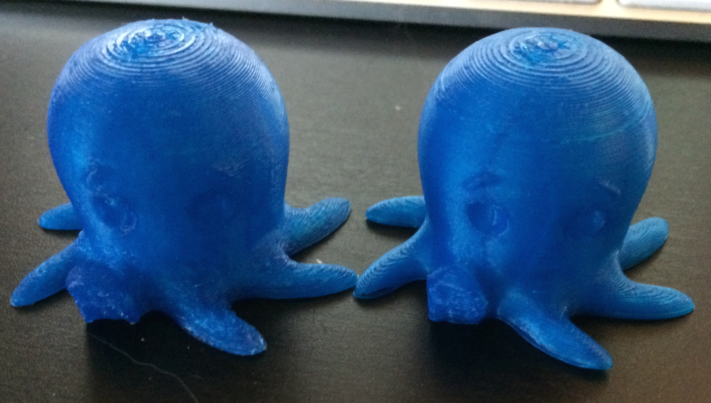
The one on the right was printed at 30mm/s for infill, outer perimeter and inner perimeters. It looks nice and took about 35 minutes to print.
The left octopus was print at 120mm/s for infill, 80mm/s for the outer perimeter and 100mm/s for the inner perimeter and took 22 minutes to print.
While the right one is obviously a cleaner output from the machine, the left one is still quite nice and a lot better than some of the prints I’ve seen. My other machines could never hope to produce something so nicely at these speeds.
Also note, this was the first try – I only changed one setting, so more tuning can and will be done.
For contrast, this blobby looking print was done at 60mm/s for all speeds, before I adjusted the acceleration configuration:

Things are progressing quite nicely.
by B Cantin | Mar 26, 2015 | Gemini 3D Printer
After rebuilding the extruder’s filament pusher three times due to it’s penchant for ejecting the pneumatic pushfit connector, I was finally able to get it to behave, at least at lower speeds. I’ll be designing my own instead of using an existing design at some point since the current pusher is simply too unreliable and badly designed to consider using at the speeds the Gemini is capable of.
However, all that being said – it was time to test the machine out on a larger and longer print.
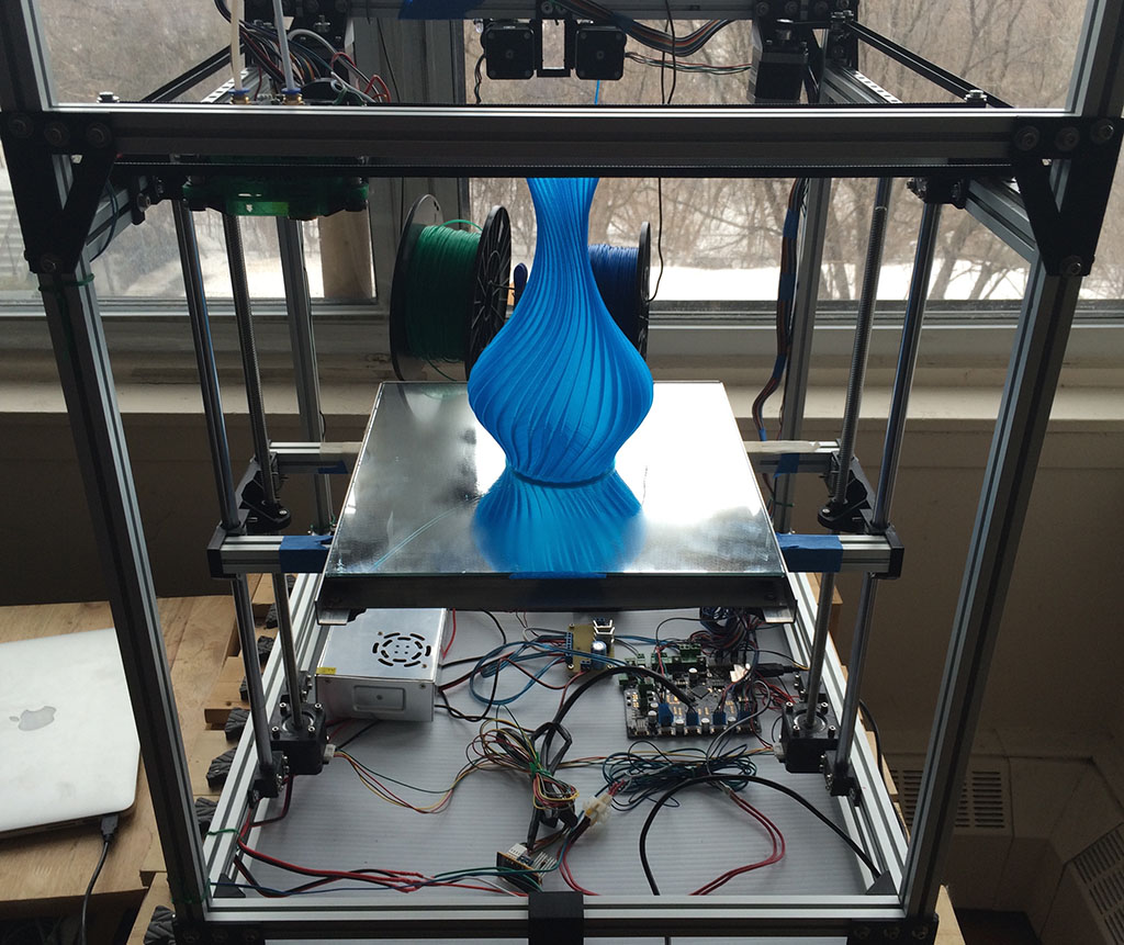
This vase is 228mm tall, and 143mm in diameter. It was a test for bed levelling (larger prints need a very level print bed), Z endstop calibration (due to the methods used, there needs to be a software adjustment made to find the correct zero point) and positioning consistency.
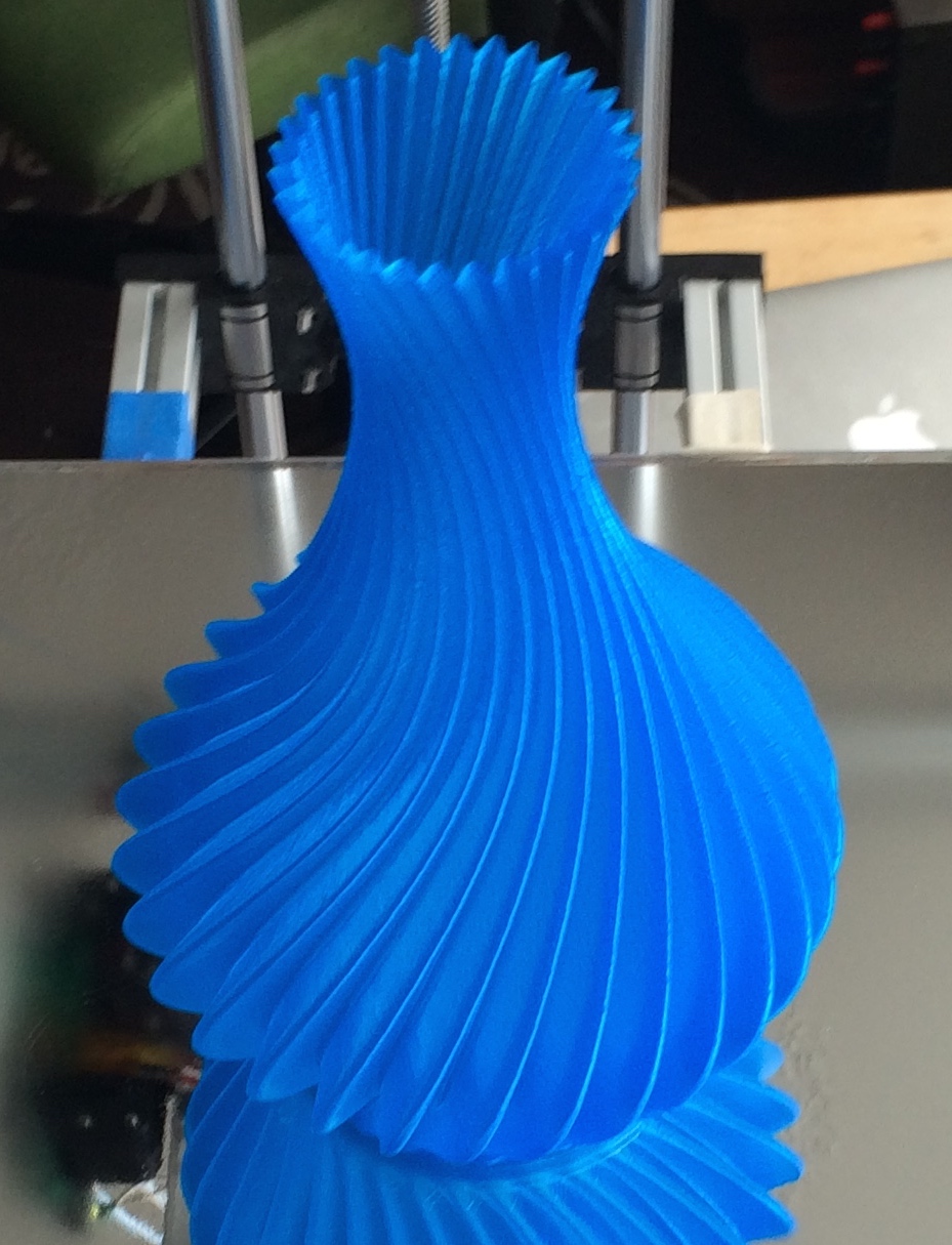
As you can see, the Gemini prototype is performing quite well!


Recent Comments