by B Cantin | Oct 31, 2015 | Gemini 3D Printer
Using OpenSCAD to recreate – and hopefully finally finish – the X-Carriage design has been proving beneficial.
It’s now much easier to programatically place the parts in a mockup of the assemblies and see how they’ll fit – and most importantly, I can make parametric adjustments to the placing and have the design automatically reshape itself to match.
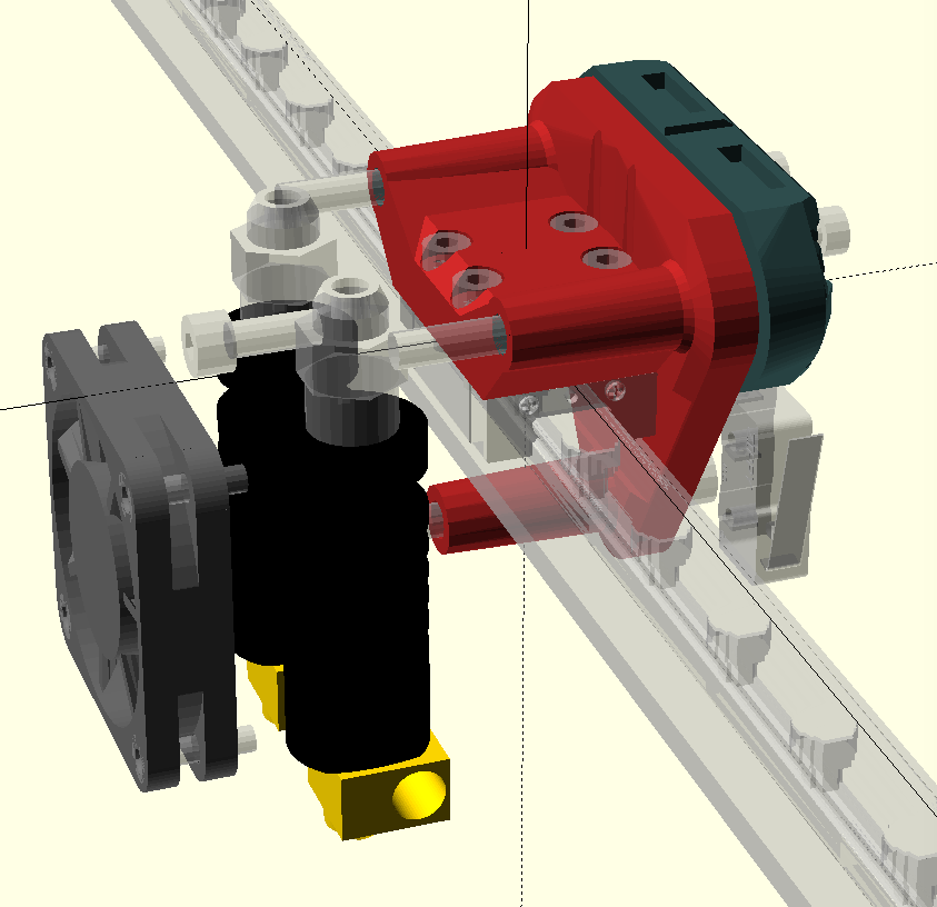
As you will see in the above rendered view of the X-Carriage, it’s starting to get pretty busy with components.
The goal here is to get everything to fit in as small a space as possible but still end up with printable parts.
What this partly entails is that components cannot be so close together that the ensuing printed part has thin walls or impossible overhangs
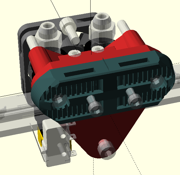
The belt clamp shown below is already pretty detailed with small design elements, these can be tricky for a 3D printer, so I’ve had to do some test prints to verify it is actually printable (which it is.)
– There are still several mounting bolts not included within the rendered design and modules need to be written for rendering metric nuts and carving out insertion points for them.
– A 50mm blower fan needs to be somehow squeezed into this assembly as well, in order for the printer to also support print cooling for plastics like PLA.
– A more accurate (and parametric) version of the pneumatic pushfit connector needs to be drawn to give a better concept of the size and shape of the part.
– As described in my previous post regarding the X and Y axis end-stops, the X end-stop is shown in it’s approximate new location, the parts will need to be extended to have mount points for this switch.
I have plenty of ideas for how the cover for this assembly can be made, however they may change once all the hardware is accommodated for and the resulting shape can be determined.
by B Cantin | Oct 29, 2015 | Gemini 3D Printer
As I discussed in my previous post, work is being done towards creating an OpenSCAD parametric version of several key complicated assemblies within the Gemini 3D printer.
Things are going well – I have designed a basic syntax and part numbering system to keep assemblies organized and I have created the basis for a hardware utility library.
After recreating the current X-Carriage components in OpenSCAD, I performed some test prints of the parts to ensure the math was correct and the parts fit as intended.
While working on the new design I finally had to wrap my head around where the heck I was going to mount the X axis end-stop switch.
So much of my time was spent drawing and then redrawing concepts for the X-Carriage and Hotend-Assembly in Sketchup, I had really just put off and avoided the end-stop question.
The one thing that I had decided for certain was that the end-stop switch would be mounted on the X-Carriage and move with it in order to run the wiring through the whip harness rather than create another whip on the Y axis.
The trouble really revolved around two factors – where to even fit the switch with so many other bits of electronics built into the X-Carriage and Hotend-Assembly. It’s a pretty busy part with lots of external bits bolted and clamped into it – space is at a premium and the flow of heated air around the plastic is critical.
The second factor was the ability to make it adjustable – I was thinking along the lines that all axis have a simple thumb screw in an accessible location to allow for fine tuning of the home position.
This was becoming quite the brain teaser for me until I realized this afternoon that I could entirely eliminate the adjustment controls from the hardware and perform the adjustment with software.
I then realized I could do the same with the Y axis as well and both end-stops become limit-switches preventing a crash and allowing for homing of the machine.
The provisioning process is fairly simple – home the print head (the Gemini homes to MAX) and then measure the distance between the 300,300 point on the print bed and the primary nozzle in both the X and Y directions. These two numbers can be input into the firmware as a relative offset value. This process could be quickly repeated until an accurate value was determined through calibration.
When the print starts, it homes the print head and then print bed and then starts the print on the correct location on the print bed using the calibrated offset.
I believe it makes sense to still use a manual home adjustment on the Z axis because the print bed height is more likely to be variable. Changes in print bed coverings and materials can create large variances for the Z axis homing location. It will be less time consuming to use a spring-loaded thumb-screw rather than the software to make these frequent tuning changes.
For the X-Carriage end-stop, I am now planning to mount it below the belt line at the back of the X-Carriage. The switch holder will be integrated into the belt clamp component which is bolted to the X-Carriage base component with long M4 bolts.
by B Cantin | Oct 26, 2015 | Gemini 3D Printer
While reviewing certain aspects of the Revision 2 design for the Gemini 3D Printer a few minor design issues have come to light.
Unfortunately for this project, I was busy doing other things over the course of the Summer and needed to take a break from this machine.
The Devil is in the details they say and some of the design semantics of the X Carriage and Hotend Assembly have gone through many stages to evolve to their current state. While the modular design of the current components is pretty decent, I feel it can be made more elegant and functional with a re-working of how it assembles to the printer.
I spent a chunk of time over the past few months learning how to make complex parts within OpenSCAD to allow for easier revisions of designs and parametric settings to allow for hardware variations. This new skill will be used with the redesign of the Gemini X-Carriage and Hotend-Assembly.
The source and printable parts are being reorganized into sub-system components and a private JIRA instance is being created for task tracking and documentation. These steps will bring a more orderly development approach to the creation process.
Since the primary goal of this project is for me to have a machine with the size and capabilities of the Gemini, some of the focus will be changing in terms of the design scope for this prototype.
Enough will be changing that I suspect that this will become Revision 3 of the Gemini 3D Printer and Revision 2 will become just a stepping stone from the initial proof of concept prototype to a more complete system.
by B Cantin | Jul 9, 2015 | Gemini 3D Printer
It’s been a slow week or two for updates on the Gemini 3D printer project, I have not as much time to dedicate to the project as I would have liked, such is life.
I have been putting what time I’ve been able to spare on optimizing the electronics configuration for the printer.
Modifications were made to the 24v to 12v regulator daughter board to also output 5v for powering the Smoothieboard, however I have ultimately decided it is going to be easier to eliminate this set of circuits altogether.
The reason for the 12v regulator circuit was to enable use of fans that I already had in stock – all of my previous printers ran on 12v supplies. I ordered replacement fans for the machine in 24v models to simplify the configuration now that I have a solid idea of what fan types and sizes are required.
The first of those fans arrived yesterday, which was earlier than expected, and is a 50mm cage type blower – this will be used for print cooling.
I am awaiting the arrival of another package which should contain a 40mm fan for cooling the cold end of the J Heads as well as a pair of 120mm fans which will provide cooling for the electronics and the stepper motors.
While doing the wiring layout for the electronics I found that I was short one or two of the 5mm screw plug connectors for the Smoothieboard.
Thankfully Arthur (one of the Smoothieboard designers) was able to point me to the Bill of Materials for the board so that I could find the part number for these connectors.
Digikey had them in stock and offered 1-day shipping of them, so I also added some cable covering material and the Recom 5v DC-DC regulator which can be populated to the Smoothieboard to provide it’s required 5v onboard power from the VBB input.
This eliminated the need for an external 5v power supply circuit and takes the daughter board entirely out of the design now, or at least will once the other 24v fans have arrived.
Testing has been done on the Z-axis and it seems to be working fairly well. I am considering a slight re-design of a few of the related parts, but they will stay as they are for the initial build. I hope to get the printer up and running and put it to work printing it’s own updated parts.
The current build is complete enough to provide the metrics for designing a new hotend chassis and I’ve been pondering how best to get all the parts to come together for that portion.
I have a concept in mind, but it would be best to have the new 40mm fan which will be integrated on-hand to finalize this. Hopefully it is arriving with the same swiftness that the 50mm fan did.
by B Cantin | Jun 26, 2015 | Website
Just a quick note that this site is now secured with SSL.
This is partially in anticipation of future plans to be able to offer 3D printer and robotics kits for sale directly on the site.
I am hoping to be able to provide high quality plastic parts for several popular RepRap printers such as the Prusa’s i3 and tbj1’s E1X, as well as others.
Browse the site with confidence that your connection is safe and secured.
Recent Comments