by B Cantin | Jan 20, 2016 | Gemini 3D Printer
In my last post I described some mistakes made in the Z axis design – particularly that I had not made a secure enough clamping setup on the LM12UU bearings and had also selected aluminum stock for the weight bearing arms that was not up to the task of supporting the build platform in a stable enough manner.
I have decided to correct this before proceeding with testing rather than waste my time fiddling with a clearly broken setup.
My general solution in the redesign is to overbuild the Z axis – this will remove any weight restrictions on the build platform (within reason, of course) and also allow the machine to move smoothly which should naturally translate into higher quality prints.
The second revision of the Gemini prototype used four 12mm hardened steel rods for the Z axis and moved the platform using two leadscrew motors in a similar vein to the RepRap Mendel Z axis with the difference being it used two guide rods instead of one on each side.
This design proved to be difficult to maintain level on the X plane due to the weight of the build platform and the ease at which a nicely machined leadscrew will turn. On the Mendel printers the nut-and-threaded-rod doesn’t turn turn easily with the limited weight applied to them and thus they do not tend to move on their own when powered down.
The third revision addressed this by using a cantilever design guided by two rods at the rear of the printer, leaving me with two spare 12mm rods. I am re-introducing them into the design by doubling up the linear rods on each side to create more rigidity on the axis.
I plan to replace the aluminum angle with 3/4″ square aluminum tubing which has much less flex, particularly at the lengths involved. The two square arms will be well constrained and might possibly lend itself to a three-point levelling system for the build platform as well.
I won’t have time tomorrow to work on this redesign due to other commitments, but I am attempting to get as much of it created today as I can and already have the lower rod holders being printed on my Prusa Mendel i2 as I write this.
Stay tuned, I will have pictures later this week and hopefully will be able to report some success.
by B Cantin | Jan 19, 2016 | Gemini 3D Printer
After wiring everything up and running electronics and motion testing, I am happy with with general design of the corexy system and the hotend mounting.
I ran the machine through some paces last night for several hours without any failures or signs of warping due to heat.
What was extremely disappointing was the Z axis and build platform mounting design – I had my doubts about this during construction and yesterday’s testing confirmed that there is a lack of rigidity in the whole setup. Getting the bed level is proving to be a large challenge given the amount of flex in the design.
I might be doing some more work to try to hack this into testing operation but ultimately it needs to be redesigned.
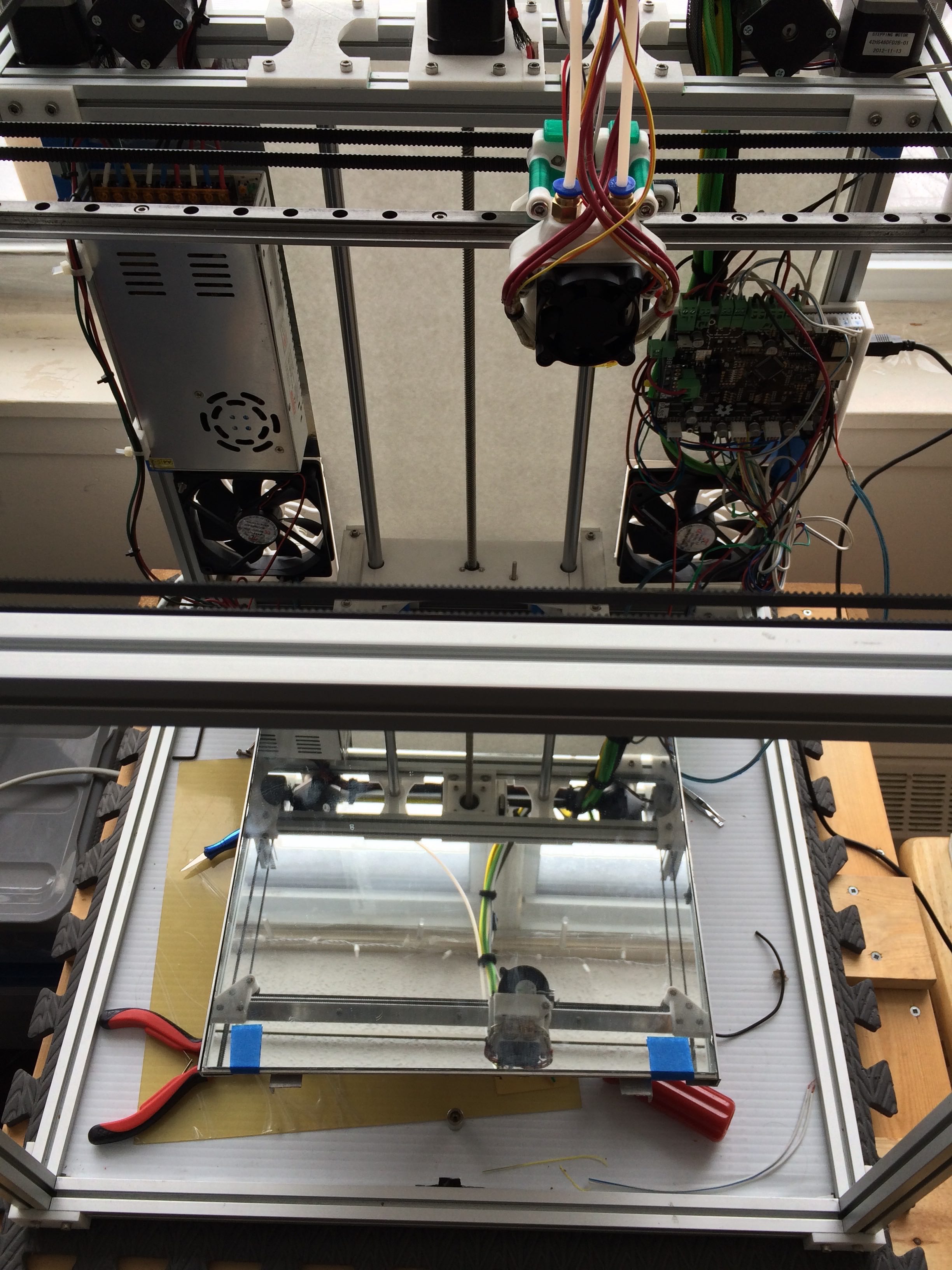
The heated bed platform is constructed using a standard RepRap heated bed which is bolted flush to an aluminum heat spreader and insulated on the bottom to retain heat. A 12″ x 12″ mirror tile from the hardware store provides a strong flat surface to extrude plastic onto.
It’s heavy. The base heating module weighs in at 970g and then jumps up to about 1620g once the mirror tile is added.
The net result of all that weight on the poorly designed LM10UU clamps and the skinny aluminium channel I used to hold it all up is a lot of flex and it’s very sensitive to vibration.
I plan to make a revised version with stronger bearing clamps as well as stronger support arms. I am seriously considering adding another 10mm thick linear guide rod or two to the design as well to enforce rigidity.
I’ll need to look at seeing what can be done to alleviate some of the weight if possible as well.
Otherwise, everything seems to be working well. There are a few more pieces which need to be added to the filament pushers so that it can actually start feeding plastic into the hotends but I don’t anticipate those will be too hard to design.

Update: I did a bit of disassembly on the build platform base – removing the glass bed guides from the assembly reduces the overall weight by 130g for a total of 1490g. Not really a significant savings overall in terms of performance of the current design. I might still try to press this into service in order to get the filament pushers finished and the printing abilities of this build tested. If I can get it printing some parts it may be easier to use the larger build volume (compared to my little Prusa Mendel i2) to create a new Z axis.
by B Cantin | Jan 18, 2016 | Gemini 3D Printer
After much revision to the X-Carriage and it’s related electronics and hardware mounts I finally have something I believe is a viable prototype.
This leads to the great fun of many hours of wiring and testing the electronics.
Aside from an issue with the X axis endstop connection everything seems to be working as designed. The corexy movement is working well and the hotends are both heating correctly, with automated cooling fan turning on if either hotend gets warm enough to warrant it.
A few more parts need to be designed for the filament pusher and the heated bed platform has yet to be mounted to the Z axis, but the third revision design is getting close to being a 3D printer again!
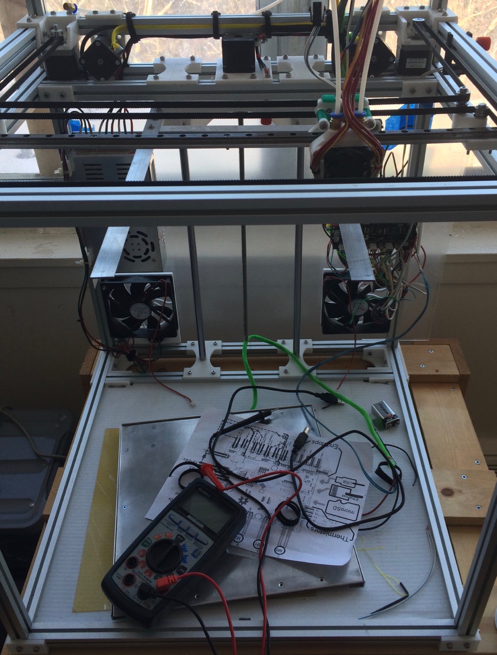
Rather than tease with more OpenSCAD or Maxwell renderings, I thought I would show a photo of the actual prototype, partially assembled and mostly wired up:
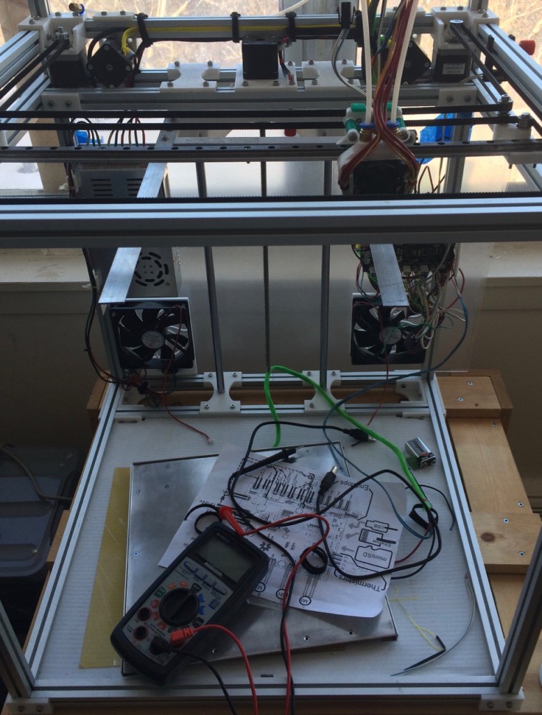
The modular design of the X-Carriage shows off a couple of it’s benefits for fixing the X axis endstop. Some testing with the multimeter indicated that the switch was working fine and that the problem was somewhere within the length of wiring from the microswitch and it’s quick connect.
Because the carriage assembly is modular I was able to remove the portion of the carriage that holds the switch and not have to remove all of the other components from the printer. Further examination revealed that one of the wires had broken at the solder connection, likely due to repeated movement during various assembly tests. Quick bit of soldering ought to rectify the problem.
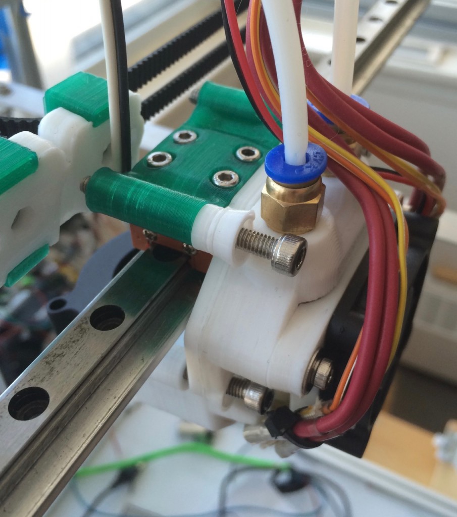
Here is what the x-carriage looks like with that portion removed – note that the belts remain clamped in place and tensioned while everything is apart which is a real time saver:
by B Cantin | Jan 17, 2016 | Gemini 3D Printer
In my last post I described many changes and goals I was seeking to achieve with a redesign of the X-Carriage for the Gemini 3D printer.
Admittedly this process has taken much longer than I ever anticipated, which has been disappointing.
After the first working prototype of the Gemini that I created in early 2015, I figured it would take me at most a couple of months to get everything optimized and a new revision of the 3D printer running and printing.
Little did I know how much I had really tasked myself with and the learning curve that I would have to experience. Redesigning the corexy mechanism and the frame took relatively little time, I figured I was well on my way to a more refined machine.
Using SketchUp for the design turned out to be a major time suck for the project. I had to go through a great number of concepts and revisions to get all the electronics to fit into the smaller space I had allowed for when I redesigned the corexy mechanism and frame layout.
Making dimensional and part-placement changes with SketchUp entails a ridiculous investment in time, manually editing vertexes and shapes to compensate for SketchUp’s primitive modeller. It’s not that you cannot make complex models in the program so much as the amount of extra work that is required to make those objects exportable as manifold STL files. At some level of complexity it becomes nearly impossible, and I found that I could make objects mostly manifold and then run them through Netfabb to fix the remaining glitches. Thankfully I’ve been doing most of my slicing with Cura and it’s fairly good at fixing most minor STL file glitches. Slic3r, despite it’s major improvements over the years, is still generally inadequate at compensating for the most minor of manifold issues within STL files and more often than not crashes entirely when loading models exported from SketchUp.
Over the summer I got busy with other projects and also suffered from some health issues which prevented me from making any major progress on this particular design. Too be honest, I also got fed up with SketchUp and the overwhelmed with the challenges of coming up with a working model for the X-Carriage in it.
I took many months off to learn OpenSCAD and make some items with my 3D printers which were not other 3D printers.
By October 2015 I thought I was ready to start back at it – and I started where I left off in early Summer and recreated some of the core portions that did work in OpenSCAD. Once I got the basics going, I then took another break. I was actually fairly stuck and temporarily out of ideas. Work and health issues took precedence, my employing company was acquired and there has been a transition period ongoing and I was in nearly constant pain from RSI. I won’t focus too much on the RSI, but suffice to say I invested my time and money into changing many aspects of my ergonomics and lifestyle to heal from years of damaging behaviour and I am happy to say that I’m am mostly pain free and able to once again focus some time on this project.
As the fall season transition into Winter, I had managed to build a modular parametric code framework for the X-Carriage in OpenSCAD. I took advantage of a couple of free days during the Christmas holiday season to pound out some rough test pieces and print them to get a feel for how it might all work together and how to best compensate for the absolute math of OpenSCAD dimensions and the reality of extruded plastic. I got side tracked by some fanciful designs before I managed to reign myself back to reality and come up with the modular compact carriage concept I’ve detailed in the past few posts.
I am happy to say that today marks a milestone where I have all the electronics mounted within a printed assembly and mounted to the robot. I see many points of the models that I would like to improve on aesthetically and some minor modifications for part fit and placement, but it’s together well enough to start wiring things up to the Smoothieboard and start some movement and heating tests later today.
Based on the current design I can now finalize the placement for the build platform, relative to the nozzles, and create the final missing part or two for the filament pushers. After the trials of the past year, I loath to put a date on when I expect the Gemini revision 3 to be actually printing objects – but I think it might be safe to say “soon”.
by B Cantin | Jan 9, 2016 | Gemini 3D Printer
After much experimenting with OpenSCAD for the X-Carriage I have quickly learned how powerful a tool it can be for developing complex parts.
I was coming up with some interesting concepts for wrapping extruded plastic around the various hardware and electronic components over the holidays which gave me some inspiration towards how best to create the X-Carriage and hotend assembly for the Gemini 3D printer.
The first aspect of the new design is a slight expansion in the width of the overall carriage assembly. My goal was to have the x-axis endstop attached to the carriage so I created some quick test parts to determine a comfortable amount of clearance for everything.
The x-axis will home to MAX on the right side of the printer. The endstop microswitch that is mounted on the carriage will trigger when it meets the x-end/y-carriage component on a conveniently located flat edge already existing on the SketchUp designed component.
The distance between the left hotend nozzle and the right edge of the build platform when the carriage is homed to MAX can be measured and then configured in the firmware – more on this later.
Most importantly with this configuration is that the GT2 timing belt clamps are not too close to the idler pulleys in order to avoid over stressing the drive belts.
The secondary goal was to have both hotends parked outside of the build area when homed. My reasoning for this behaviour is that bowden style extruders have a greater tendency to ooze plastic while idle than direct drive systems. Dual material 3D printing with both hotends side-by-side in this manner has the caveat that at any given point during the print there is always an idle hotend moving around build area and over the object.
To mitigate this there are two strategies that can be both employed if the hotends can move outside of the build area. The first is that the idle extruder can perform a filament retraction and then lower the hotend temperature several degrees. Changing materials requires performing the same procedure on the other hotend and then raising the temperature of the previously idle hotend to extrusion temperatures. The filament is then extruded a certain length to prime the hotend for printing immediately.
The second strategy is to have a brush or similar wiping point mounted, necessarily, outside of the build area. The carriage will pass over this point and wipe any excess filament off the nozzle tip before returning to the build area.
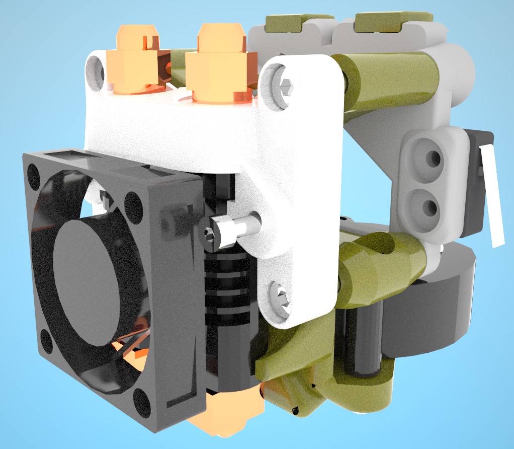
Finally, it would be best is the design was also easy to disassemble to allow for easy maintenance, modification and customization. I designed a working model for mounting a high CFM 24v DC blower fan that would direct the air as close to the print as possible while minimizing the airflow directed at the hotend heating block. I realized that with OpenSCAD it would be easy to add some variables to the code which would allow me to adjust the fan location, relative to the carriage, and have the output vents remain in the same position.
This led me to centre the blower fan at its middle, rather than the output channel. By switching from a three bolt assembly for the carriage to a four bolt design I was able to separate the blower casing from the linear rail carriage mount portion of the carriage. These two components are held in place by a front and rear bracket with space to add items along the bolts at the front and the back.
The benefit of this is that parts can easily be replaced by loosening four M4 bolts a few millimetres and then pulling them out of the front of the carriage. If the x-axis linear rail assembly needs to be changed for something taller, such as an L type profile, changing a few variables in the script and replacing the brackets and the hotend assembly are all that is required.
I have produced an incomplete set of test components that achieves all of these goals and fits in the available space. Much work is needed to be done still, and not all parts are shown – but this mockup rendering should give an idea how these ideas are starting to come together.

Recent Comments