by B Cantin | Feb 10, 2021 | Uncategorised
When I completed the last test build of the Gemini 3D Printer I found that although the CoreXY mechanism worked well – the Z axis still left much to be desired.
The print bed was quite heavy and hard to keep level when the motors were idle and the weight wanted to slide the bed downwards.
I then built it using a cantilever bed which solved the levelling issue but I then found that any fast moment of the print carriage introduced unacceptable level of vibrations which were amplified by the cantilever mechanism.
Around that time, the market became flooded with cheap shoddy 3D printer kits (they’ve gotten better since 2016, to be fair, but it was a crap-fest at the time) and I was unwilling to invest further into the R&D of a CoreXY bot design that it was clear I was never going to be able to sell at the price point I intended, especially if the Z axis solution was going to need more expensive parts than the initial prototypes.
I learned some better CAD software and decided to put aside the designing of 3D printers since it had become an all-consuming activity for a while and was rapidly becoming nothing more than a money-pit instead of a business investment due to the aforementioned market changes.
I’ve made plenty of cool things in the meantime with my upgraded Prusa i2, but lately I have found that the limits of it’s 200x200x100 print volume has become a liability so I dusted off my stacks of aluminum extrusion and boxes of 3D printer parts and I am taking another crack at it.
This time, the goal is to assemble the best of the parts I have with a few newer components into a much simpler and time-proven format and also to use up some of these R&D materials which aren’t doing me any good sitting around.
To this end, the new machine will be aiming for a 300x200x300+ print volume and use the same orientation of the moving axis as Prusa’s printers do.
The main differences between mine and the average Prusa clone (aside from the larger volume) is that the frame is entirely enclosing the mechanism, allowing for a warmer and quieter build chamber and I’m using appropriately sized 12mm linear rods for the guides.
This has been coming together quite quickly, starting with the initial idea at the end of January to a nearly assembled robot by mid-February. Pictures and more details will be coming soon.
Also in the works, check back for some new content that I am preparing related to 3D printing of RC cars and Beetleweight (3lb) combat robots.
by B Cantin | Jun 27, 2016 | Gemini 3D Printer
After getting the latest prototype of the Gemini 3D printer up and running I was dissatisfied with the assembly, implementation, appearance and performance of the overall system.
I starting playing around with some ideas in Sketchup by moving bits around and fiddling with the layouts and came to realize that I could eliminate several of the aluminum extrusions and reduce the overall materials cost as well as exterior size of the machine.
A few new parts came together really fast once I started reimagining the overall frame design
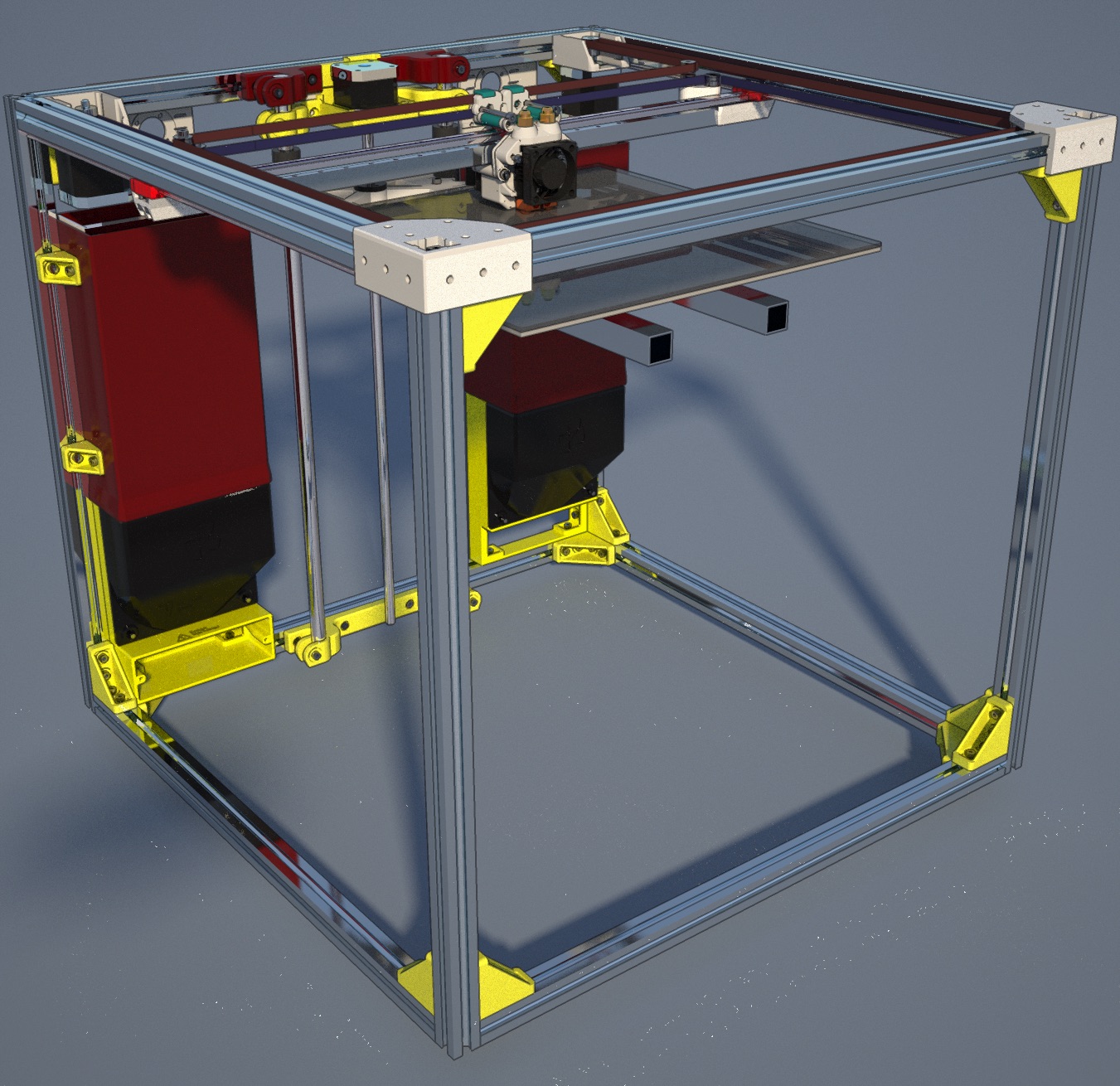
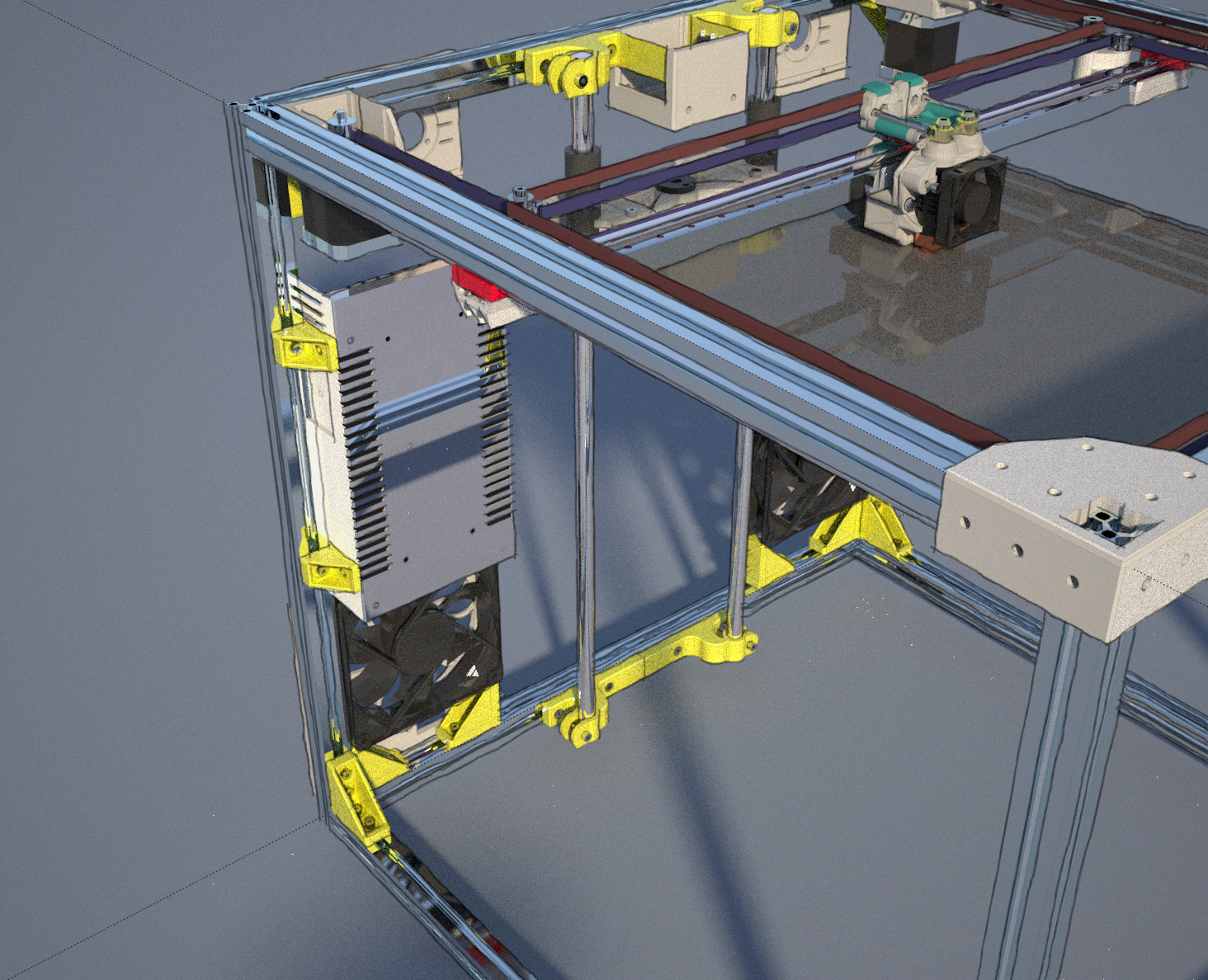
- New corner bracing – the first design did not work well, the second design worked better but turned out to not have the requisite strength or aesthetics I would have hoped for. Assembly was a chore to deal with if parts needed to be changed out. The new corner braces are a more traditional style but have been 3D printed in ABS with thick perimeters to make them strong and less brittle.
- From the new corner brace design I created a new 120mm fan mount with the AC plug and switch integrated as with the last prototype – however the part now forms a protective box around the live AC wiring and I have designed a fan duct to redirect the air vertically into a channel which will cover the power supply and direct the air towards the left corexy drive motor and extruder motor.
- With the new compact frame design I needed to come up with a new way of mounting the vertical smooth rods for the Z axis – I came up with a snap-fit connector which uses and M4 bolt to clamp the rod in place. By using these clamps I will be able to ensure correct and sturdy alignment of the linear axis is something that is easy to achieve. Disassembly and servicing the axis will be greatly simplified with these parts.
The new clamping system also permits the effector to move towards the back of the printer by over 20mm more than it could previously – this allows me to move the bed that much closer to the linear rails which reduces the lever/fulcrum effect of the moving platform.
- Some basic repositioning of the effector parts is also necessary – the flat aluminum stock which I used for the Rev 3 prototype is not stiff enough to prevent the X axis linear rail from sagging towards the centre which causes uneven contact with the bed across the width of the print area. I will be replacing this assembly with the one from the previous build where the linear rail was attached to a 3 sided aluminum channel, or potentially an L shaped channel for more rigidity.

In the rendering shown above, all of the non-white and non-green plastic components are part of the revised configuration.
The overall CoreXY component of the current build is satisfactory and thus will be pretty much remaining the same, aside from the modified X axis support and some cosmetic revisions to the printed components.
by B Cantin | Jun 22, 2016 | Gemini 3D Printer
Work on the Gemini 3D Printer was on hold for a few months while I used it’s cart as a temporary plant nursery for my garden.
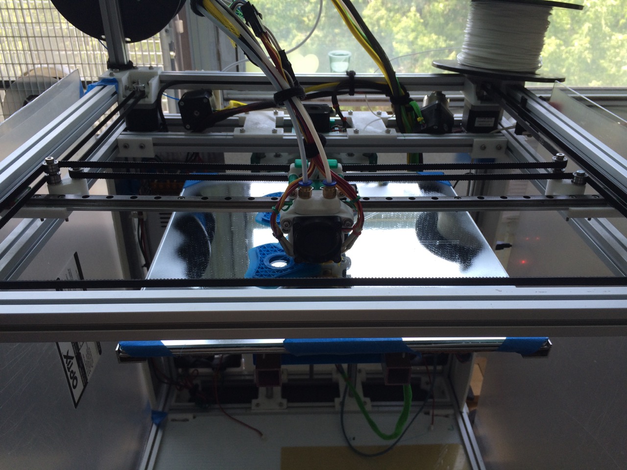
I created a few quick parts to get the bed mounted to the Z axis and get the machine up and running for some testing.
There have been a few print quality issues but they look to be mostly software tuneable items thus far. The machine has been able to print in both ABS and PLA.

Gemini Printing ABS
Overall, I’m not as enthused with the final assembly of the prototype as I would hope to be – although I am excited to have the unit working so I can properly test the design out.
I believe I could make the machine more compact, easier to assemble and maintain, sturdier and still reach the basic print volume I am aiming for of 300mm X 300mm x 300mm+.

Partial artistic concept for revision 3.2.0
A quick bit of Sketchup work yesterday fleshed out how a rebuild of the rear of the printer could take shape.
by B Cantin | Mar 8, 2016 | Kitchissippi-Delta
As I detailed in my last post – The Kitchissippi Robotics 45 Degree Linear Carriage (A brief history) my unique linear carriage design has gone through off-and-on revision and evolution over the past two years or so since I first came up with the idea.
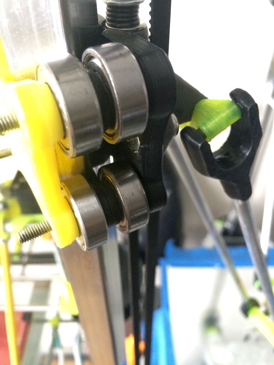
The latest revision is certainly the most refined – it retains the elegantly simple design of the previous conceptual parts – eight bearings constrained with four bolts around a steel tube at a 45 degree angle.
What I added in this version is adjustable tensioning of the bearings against the tubing. The major drawback of using bearing holders that clipped the bearing in place was that it was nearly impossible to adjust the tension and keep things squared away, and the bearings wanted to shift. They need to be constrained on both sides.
The problem with using plastic spacers is that it’s hard to get perfect accuracy in the thickness of them – the first layer could get squashed down a bit into the print bed and change the height of the spacer from the original CAD design.
I mostly used metal washers as spacers but they have the problem of being able to only add or subtract the spacing in 1mm increments. Getting the bearing spacing against the tubing was terribly inaccurate using SketchUp. They were either too loose or too tight and gouging the metal.
I redesigned the parts in OpenSCAD and parametrically adjusted the math until I got a more ideal design. Then I assembled them using rubber spacers to allow for fine tuning of the spacing between the bearings and the tubing.

This seems to be the most winning combination of the design so far – it rolls stiffer and straighter against the tubing while still being gentle enough to not damage the tubing.
I’ve also spaced the lower bearings further apart and more inwards to provide a more stable rolling platform.
Also of note, I ditched the separated bar design of the outer carriages from the previous version. Once the arm joints were fully stabilized the stresses of the delta mechanism cased them to flex.
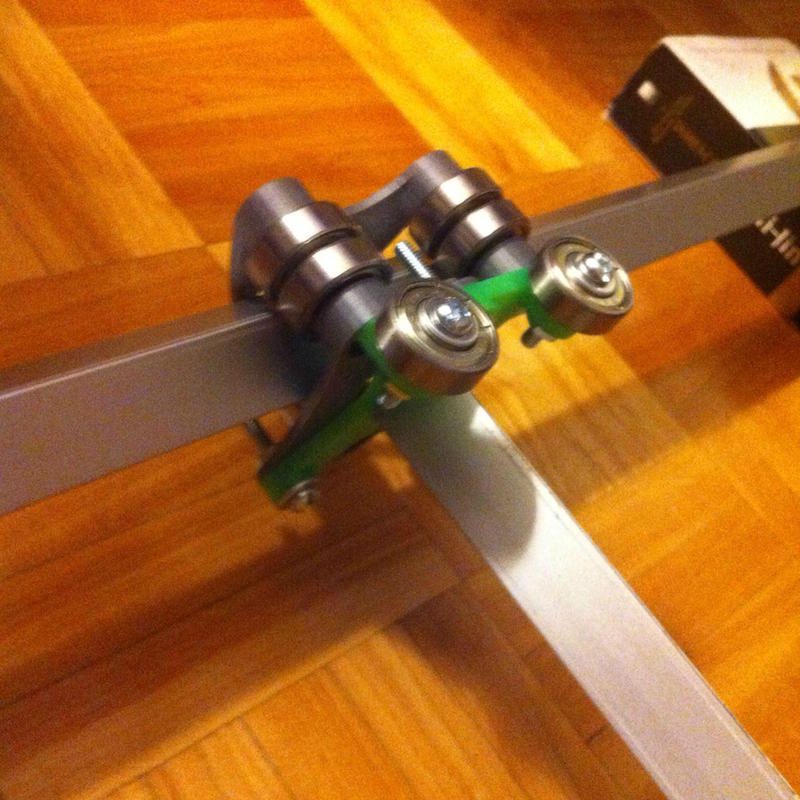
Above is the X tower carriage which is working well. I am in the process of printing the last few pieces for the Y and Z towers.
Ignore the length of bolt ticking out of the carriage – I thought I had the appropriate N06 bolts on hand for these but cannot seem to find then. I believe I may have used them in another project, so I grabbed some M4x40mm bolts to put it together. They are similarly sized and it will do until I can get to the hardware store and get the slightly shorter bolts I had intended to use.
For comparison here is the previous working design that was less stable:
by B Cantin | Mar 8, 2016 | Gemini 3D Printer, Kitchissippi-Delta
This linear carriage design is something I have been toying with for several years now.
It all started with having picked up a bulk lot of 608zz skate bearings with the intent of making a Rostock or similar delta printer some day, but mostly because I needed a few for my Mendel and at 30 cents a bearing for a hundred bearing I felt I couldn’t pass it up – I’d find a use for them.
I was actually working on the early proof of concepts for the K02 corexy printer I wanted to build when I came up with the idea of turning the square tubing 45 degrees. I had picked up some stock aluminum 3/4″ tubing at the hardware store to play around with and was trying to work out a simple method of utilizing them as both the frame and the linear guide using the skate bearings.
The main challenge was that the bearings need to be preloaded to an extent and most methods of getting them tensioned against the tube and constrained well enough to function as a linear guide required a great number of bearings. Such a mechanism gets quite large when dealing with skate bearings and typically requires less common bearings that are smaller.
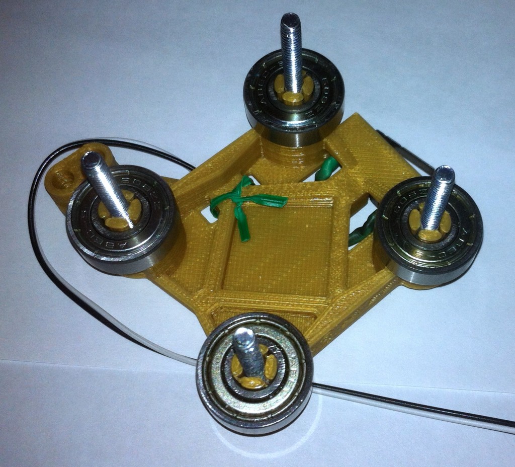
I have no record of how long I spent just rolling bearings in various configurations along the aluminum stock and daydreaming until I stumbled across this trick, which I believe is unique to myself, of pinching an edge of the tube between two skate bearings to form a point on the linear guide. I recall that I printed various small plastic parts to test my various ideas which was an introduction to designing custom parts in SketchUp as well as proving the usefulness of rapid prototyping that can be achieved with a 3D printer. Any idea I had could be test implemented within a matter of minutes or at worst hours depending on the size of the part.
I quickly whipped up a linear carriage design that used three bearings mounted on a plate and a mirror of that held together with four bolts to form the linear carriage. I expanded on this and built a corexy stage with crude but workable filament drive made from reinforced fishing line.
This is an early prototype of the design, intended to be used with a CoreXY mechanism:
It worked fairly well and was able to plot out shapes reasonably accurate from g-code output from Slic3r. I had some initial concerns about the longevity of the soft extruded aluminum tubing verses the hardened steel edges of the skate bearings, as did those I shared the concept with on the #reprap irc channel.
After about 10 hours of running the mechanism it became apparent that the bearings tightened down to the point they’d be accurate linear mechanisms was eating deep gouges into the tubing and would need to be constantly tightened (by pulling the plates closer together) until there was going to be no tubing left.
Here is a picture of an early test build of the design:
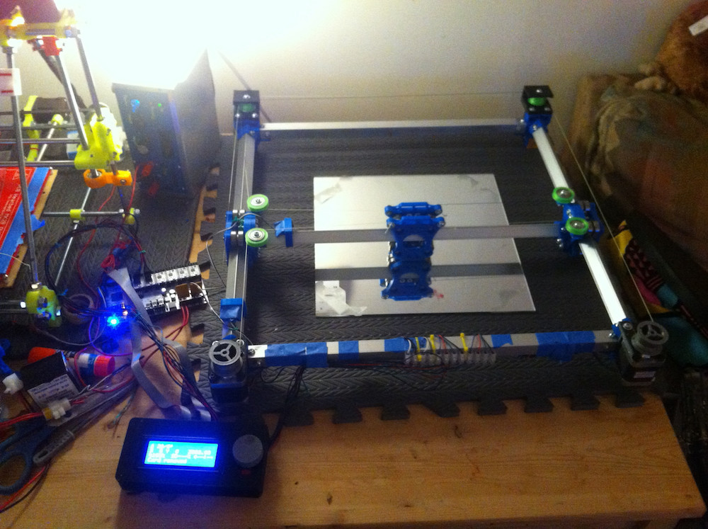
There are issues with the overall CoreXY mechanism shown, there are non parallel drive lines at the rear which would cause accuracy issues over the course of a print. It’s running on a RUMBA controller board and powered by my home made 12v lab supply, sitting beside an earlier build of my trusty Mendel. This is early in the testing and the aluminum tubing has yet to be eaten by the carriages. I’d already switched from a 3-per-side bearing system to a 4-per-side bearing system by this point to deal with binding issues caused by the stresses of the tensioned drive mechanism.
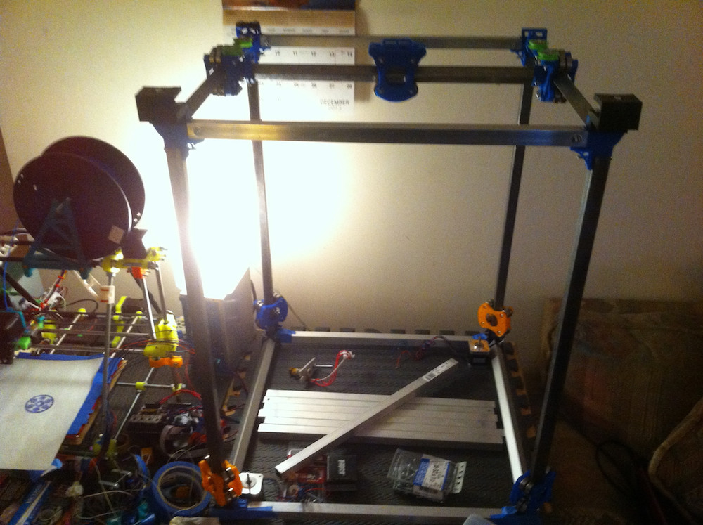
Work proceeded rapidly and by December of 2013 I had the above mechanism in place with steel tubes instead of aluminum on the moving axises and some ideas as to how to attempt a Z axis. The drawing on the piece of paper sitting on the Mendel’s bed was done by the steel version of the gantry and shows how much this concept dwarfed it.
I got so far as to mocking up a few Z axis designs for the CoreXY before I finally had to admit a bit of defeat that the moving weight of the carriages and the steel cross bar, as well as the Z axis variations were not going to meet my goals of a fast large format 3D printer. It worked, but it was going to be a slow machine – and I was not entirely convinced the simple filament drive system was going to be accurate without some serious reconsiderations. This project had started in late 2013 and I had started to question of the wisdom of filament drives in spring of 2014. GT2 timing belts were only just starting to flood the market, there were a lot of us playing with filament drives up to that point and running into certain concerns about positional accuracy with the windings on the spools. Timing belts were becoming cheap enough that the price was comparable to fishing line that was strong enough for RepRap usage and comes with easier repeatable motion.
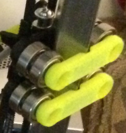
I had one last concept to try before I gave up on the big CoreXY machine – I wanted to make the carriages thin and remove the extra washers that I had been using as spacers between the two halves of the carriage. Above is a prototype of a snap-fit bearing holder system with an integrated end-stop and drag chain holder. This was not easy to design in SketchUp and I started to consider learning OpenSCAD around this time. The snap fit bearing holders were also a bust – the bearings really need to be constrained around their hubs from both sides in order to make this system work. Since it’s a unique concept, I wouldn’t have known unless I tried.
I decided there was going to have to be a better way to build a CoreXY printer, but thought the linear carriage would be particularly suited to a Delta style printer mechanism. Below is a side-by-side comparison of how the K02 mechanism became the K03 mechanism that I was using for the past 2 years. (right to left)
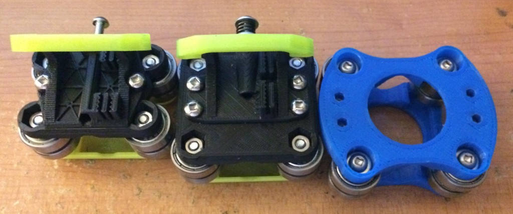
The final version on the left turns out to not be that final. It was an exercise in minimalism which carried onto my next project, the very first version proof-of-concept version of the Gemini 3D printer. Much like the first Gemini build, it proved that you can indeed building things too thin with plastic. The linear mechanism shown above did work for a time, but the printer ran into other problems and I got focused on other things, such as the Gemini.
It’s worth noting that the leftmost mechanism was still in place in the past week when I got the K03 Delta running again. Only the swivel and adapter portion were replaced.


Recent Comments