by B Cantin | Feb 25, 2016 | Kitchissippi-Delta
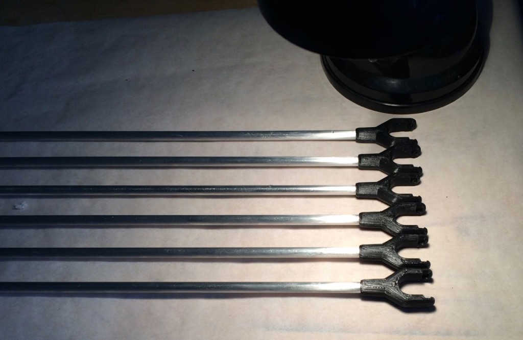
As I described yesterday evening, I have made new rod-ends for the Kitchissippi-Delta and the 5-minute epoxy seems to be anything but 5 minutes for curing time. Twelve hours later the joints seem quite strong but are not quite hardened yet.
I am pretty certain that the mix was incorrect between epoxy and the hardener chemicals, but it does seem to be slowly getting there.
I’ve aimed a small halogen lamp nearby to see if I can expedite the process. Since the parts are printed in PLA, I cannot use a lot of heat to speed the curing process without risking deformation of rod-ends.
I probably shouldn’t worry too much – it does seem to be curing, albeit very slowly, and I do not yet have a new effector piece to attach them to.
by B Cantin | Feb 25, 2016 | Kitchissippi-Delta
As my previous post discussed, I had some inspiration this week as to how to resurrect the Kitchissippi-Delta 3D printer from it’s previous self-destruction.
I have no doubt of the issue with the mechanism skewing could have been avoided by using a better adhesive to attach the rod-ends which form the clevis joints to the aluminum rod stock.
With this in mind, as I redesigned the parts, I also selected what I thought would be a more appropriate adhesive to attach them to the rods. I had on hand some Elmer’s Fix-All which has served me well in the past, so I built the rods up last night with this glue. It was a better selection than the hot-glue that was used on the original prototype, but only slightly it seems.
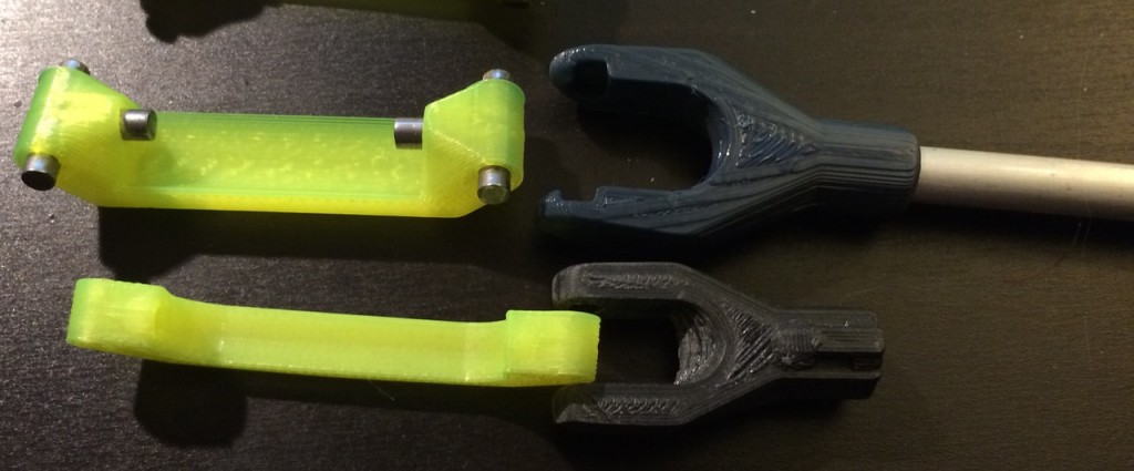
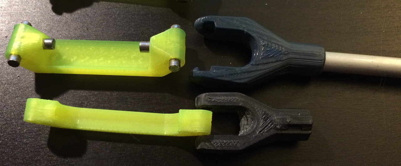
The upper swivel arm and rod-end clevis part is my inspired revision for this assembly. The lower swivel arm and rod-end clevis part are from the previous build. Although the basic design concept remains unchanged, the upper parts clearly show how the design was expanded and smoothed in OpenSCAD to form a more solid assembly.
To my dismay, there seems to have been some spoilage to the Fix-All glue, possibly due to a broken cap – the setting properties were not as they should have been. After twelve hours the glue was still soft and not even close to curing, much to my dismay.
I pulled off the worst of the problematic rod-ends, cleaned the metal with alcohol and scuffed the ends up a bit with a rough sanding block, with the hope I could repair those ends and get the parallelograms built out. I quickly found out this was folly, since some accumulated glue within the rod-ends preventing the cleaned rods from reaching full insertion, thus creating random lengths on the delta arms. Needless to say, this is not something you want – especially after spending much time hand-filing and sanding hand-cut rods to the exact same length. Ultimately this was a bad choice of adhesive, the ends that did cure pulled out with a bit of force – but not what I’d consider excessive and nowhere near the amount of force that could be imposed by three NEMA17 motors working together.
It became clear that I was going to need to pull all of the rod ends off and refinish the ends of the rods and reset them into newly printed parts. I took this as an opportunity to refine the OpenSCAD model for the rod-ends. The new model has some rounder edges, sleeker lines and more of a taper around the rod. I also introduced a new feature, which is an integrated pressure-relief channel to aid installation. Essentially this is a tiny hole at the end of where the rod gets pushed into that exits out the centre of the other side.
This pressure-relief channel allows excess glue and air that gets trapped when the rod is forced into the component to have somewhere to go, allowing for a tighter fit.
I decided to use some 5-minute epoxy this time. It should bond well and also was on-hand.
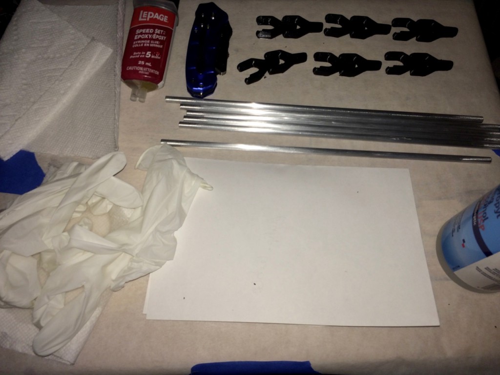
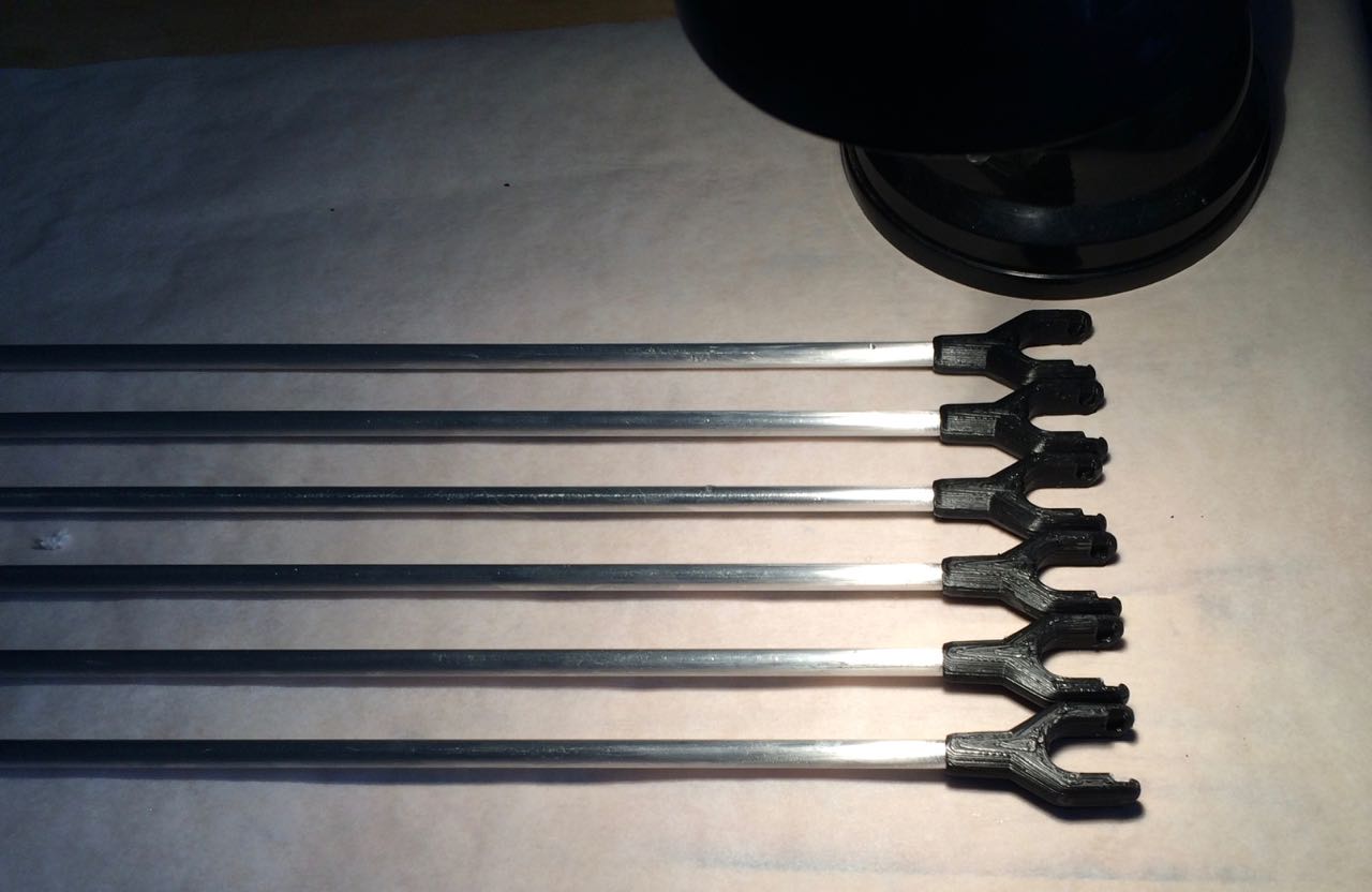
I don’t work with Epoxy much, it’s messy and quite toxic, but I spent a few minutes preparing a work area. As shown above, I have all of the rods and the newly printed rod-ends ready to go near the top right. On the bottom left are nitril gloves to prevent contamination of the rods after cleaning with the alcohol on the right as well as to protect my skin from the epoxy. Not shown are some bamboo skewers I used to mix and apply the epoxy.
I cleaned the rods thoroughly with rubbing alcohol to remove any skin oils that may be on them from handling and the ends were previously roughed up with a sanding block.
I had some trouble getting both sides of the epoxy syringe to flow evenly, but I persevered with getting the two chemicals to extrude onto the piece of paper and then proceeded to mix as best I could using a piece of bamboo. I carefully rubbed the epoxy around the inside of the printed PLA rod-ends and then pressed the rods in as far as they would go. For each rod, I then pressed them flat and level on the smooth sides created by the first layer of the 3D print. The pressure-relief holes proved their worth, allowing air and excess adhesive somewhere to go so that the rods could fit all of the way in.
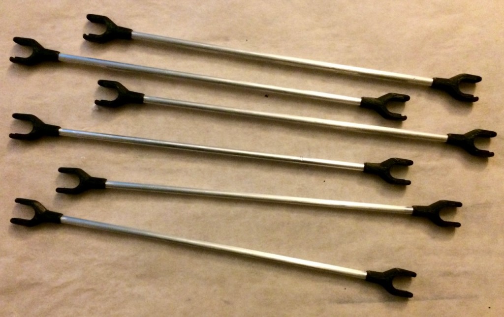
The assembly process concluded without incident – above are all six rods with their ends firmly attached.
It seems that misbehaving adhesives are the theme for this week – the “5 minute” epoxy is still tacky hours later. I suspect I got the mix wrong due to the syringe not pushing out an even mix. I’m not in a particular rush so I’ll let the rods sit overnight and re-asses the situation tomorrow. Perhaps it will set, or perhaps I’ll need to yet again print 12 more rod-ends and try another adhesive. I have some Gorilla Glue and some J-Weld on hand, either of which are contenders if the epoxy fails.
by B Cantin | Feb 23, 2016 | Kitchissippi-Delta
One evening last year the glue holding on the rod-ends on the original Kitchissippi-Delta prototype slipped due to a head crash skewing the mechanism and causing a subsequent further crash of the effector into the build platform.
Not only did this shatter the glass bed, it irreparably damaged the mechanical assembly. It was a rather heartbreaking event which hilighted some of the key flaws to the machine’s build.
Rather than re-print the smashed components and re-assemble the machine, I realized it was an opportunity to refine and fix some flaws in the initial design and build.
I noticed a few mistakes that I had made – particularly some of the hardened steel pins were not the same size as the majority of them, I must have grabbed them from a set of loose bicycle parts or accidentally scavenged a few of them from a different length of bicycle chain.
Further, there was definitely a flaw in the swivel design which allowed for too much play in the mechanism.
The 25mm fans on the effector were not providing adequate cooling for PLA prints, they either need to be moved closer to the nozzle or replaced altogether with something with a higher CFM.
I have been of the mindset that this machine should be focused on ABS printing since it excelled at that PLA cooling can be easily provided using a large externally mounted fan. I have a Hexagon all-metal hotend with a 0.4mm nozzle that I wanted to mount onto this machine with that in mind, it’s not particularly good at PLA but works wonderfully on hotter plastics like ABS. Given the long bowden system in use on this printer, ABS tends to slide more readily and not jam along the length. Fitting in a Hexagon instead of a J-Head will require a new effector, so that also entails some redesign of the parts.
Initially I had started to do some testing of redesigning it in SketchUp but was more focused on the Gemini 3D Printer project I was already working on at the time things went south on the Delta.
Some initial steps were taken to use OpenSCAD to recreate the effector but I did not get very far at the time, being fairly unfamiliar with OpenSCAD. A few aborted attempts at coming up with refined parts in SketchUp have been tried but left incomplete.
Ultimately the partially disassembled machine has been lording it’s hulking 1M tall frame over my little Prusa Mendel i2 mockingly for the past year whilst I was occupied with other things.
While cleaning up the other day I was absently fiddling with one of the swivel parts and had a sudden inspiration as to what the core problem was with the previous design. I realized that if I embedded the pins deeper into the swivel arm, fixing them on one side (rather than expecting them to rotate freely on both ends) it would greatly stabilize the mechanism as well as make it easier to 3D print.
I’ve learned much with OpenSCAD in the past several months by working on the Gemini 3D printer’s effector and Z axis redesign. Using this newfound knowledge I set about building a new project framework for the Kitchissippi-Delta and implementing some test parts.
The resulting swivel arm worked out exactly as I theorized – the pins are now adequately stable within their sockets – but what about the host component they needed to swivel on? I spent a few hours one evening recreating (and refining) the carriage adapter piece in OpenSCAD and ran a few test prints and am also satisfied with the results.
The pins sit tightly and swivel well in their constraints and the assembly mechanism is much easier to work with, no longer requiring heating or partial disassembly of the carriage to attach. Now they snap fit in with minimal pressure and a low risk of snapping the parts.
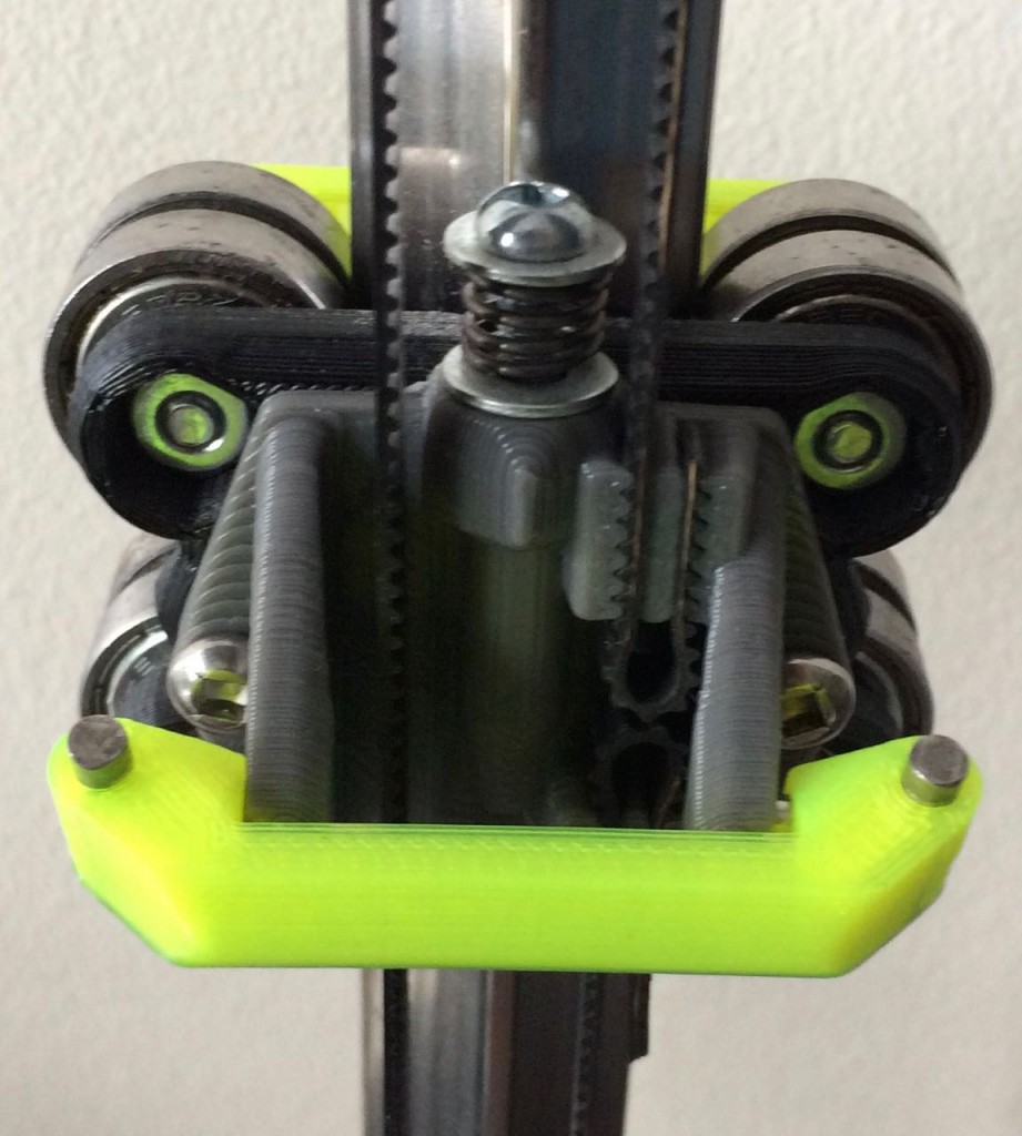
All that is left to do now is to script some new rod-end parts that will snap onto the pins and then a new effector piece. This is one thing that appeals to be about delta style printers – once you’ve made one axis, the other two are just a matter of duplicating that exact sub-assembly.


Recent Comments