Gemini Modular Compact X Carriage Design
After much experimenting with OpenSCAD for the X-Carriage I have quickly learned how powerful a tool it can be for developing complex parts.
I was coming up with some interesting concepts for wrapping extruded plastic around the various hardware and electronic components over the holidays which gave me some inspiration towards how best to create the X-Carriage and hotend assembly for the Gemini 3D printer.
The first aspect of the new design is a slight expansion in the width of the overall carriage assembly. My goal was to have the x-axis endstop attached to the carriage so I created some quick test parts to determine a comfortable amount of clearance for everything.
The x-axis will home to MAX on the right side of the printer. The endstop microswitch that is mounted on the carriage will trigger when it meets the x-end/y-carriage component on a conveniently located flat edge already existing on the SketchUp designed component.
The distance between the left hotend nozzle and the right edge of the build platform when the carriage is homed to MAX can be measured and then configured in the firmware – more on this later.
Most importantly with this configuration is that the GT2 timing belt clamps are not too close to the idler pulleys in order to avoid over stressing the drive belts.
The secondary goal was to have both hotends parked outside of the build area when homed. My reasoning for this behaviour is that bowden style extruders have a greater tendency to ooze plastic while idle than direct drive systems. Dual material 3D printing with both hotends side-by-side in this manner has the caveat that at any given point during the print there is always an idle hotend moving around build area and over the object.
To mitigate this there are two strategies that can be both employed if the hotends can move outside of the build area. The first is that the idle extruder can perform a filament retraction and then lower the hotend temperature several degrees. Changing materials requires performing the same procedure on the other hotend and then raising the temperature of the previously idle hotend to extrusion temperatures. The filament is then extruded a certain length to prime the hotend for printing immediately.
The second strategy is to have a brush or similar wiping point mounted, necessarily, outside of the build area. The carriage will pass over this point and wipe any excess filament off the nozzle tip before returning to the build area.
Finally, it would be best is the design was also easy to disassemble to allow for easy maintenance, modification and customization. I designed a working model for mounting a high CFM 24v DC blower fan that would direct the air as close to the print as possible while minimizing the airflow directed at the hotend heating block. I realized that with OpenSCAD it would be easy to add some variables to the code which would allow me to adjust the fan location, relative to the carriage, and have the output vents remain in the same position.
This led me to centre the blower fan at its middle, rather than the output channel. By switching from a three bolt assembly for the carriage to a four bolt design I was able to separate the blower casing from the linear rail carriage mount portion of the carriage. These two components are held in place by a front and rear bracket with space to add items along the bolts at the front and the back.
The benefit of this is that parts can easily be replaced by loosening four M4 bolts a few millimetres and then pulling them out of the front of the carriage. If the x-axis linear rail assembly needs to be changed for something taller, such as an L type profile, changing a few variables in the script and replacing the brackets and the hotend assembly are all that is required.
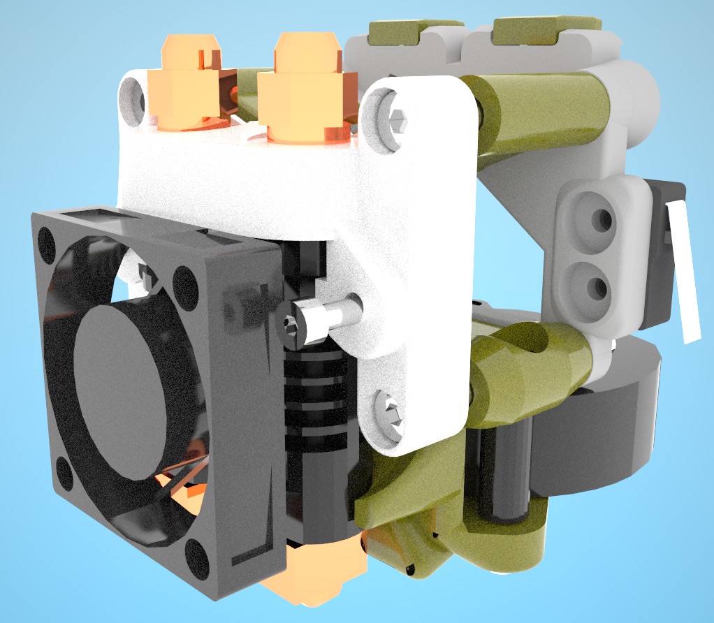
I have produced an incomplete set of test components that achieves all of these goals and fits in the available space. Much work is needed to be done still, and not all parts are shown – but this mockup rendering should give an idea how these ideas are starting to come together.
Recent Comments