by B Cantin | May 30, 2015 | Gemini 3D Printer
As per my posts over the previous days, there is a new gantry in the works for the Gemini 3D printer.
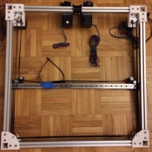
Last night the motor mounts were printed and attached to the frame. These have a lot more strength than the previous version and have slotted holes for the for M3 bolts that attach the NEMA17 stepper motors. This will allow for tensioning the belt once it’s clamped to the x-carriage, which is the next part that will be designed and printed.
Since the photo was taken I have also printed a revision of the X-end/y-carriage mounting part which corrects the belt alignment and allows for adjustment of the x-axis – I will detail that assembly in another post.
Note that the belt path is not correct in relation to the x-carriage in this photo, it will run straight like it should once the part with the belt clamps is assembled.
by B Cantin | May 29, 2015 | Gemini 3D Printer
Things are progressing fairly well with the second revision of the Gemini 3D printer’s CoreXY gantry. The new corner pieces assembled well the first time and the resultant frame is quite strong and rigid.
The former corner bracing scheme was fraught with issues of warping and it was a chore to get things completely square – this is not an issue with the new design.
A large part of why this is working is a twofold change with how the parts are designed – I have increased the thickness from 3mm to 5mm and added 1mm thick guide ridges that fit into the slots of the aluminum extrusion frame.
No photos for this post, but I should have an update later today – the motor mounts are being printed off as I write this. These new motor mounts should be much tougher than the previous ones which I anticipate should eliminate the warping issues found in the original prototype.
Getting the object models to be manifold from Sketchup turned out to be a problem, however Netfabb’s mesh repair made short work of correcting the issue. Potentially I could have spent a lot of time trying to fix up the models in Sketchup, but due to the complexity of some of the details on the part it seemed to be a fools-errand. Some things are just out of the STL export plugin’s realm of capabilities and these parts fall into that category.
The new motor mounts will bolt to the frame on two inner faces as well as the lower side of the rear span. This might be a bit of over-designing on my part, but I wanted to ensure that there was little chance for the mounts to come loose from vibrations and heat.
A small revision is necessary for the X axis configuration. I need to re-introduce the previous design’s slotted mounting system for the support beam.
The reason for this is that although the design is very accurate, the reality of mounting the parts to the linear carriages is that there is a small amount of wiggle room required to get things squared away nicely.
Currently the assembly is off by a fraction of a millimetre which prevents it from sitting perfectly even between the two sides of the frame. The result of that is excessive pressure on the Y carriages causing them to come out of alignment. This should be a fairly easy fix by slotting the four-point mounting holes on the aluminum flat bar and slotting the rail mount holes on the X-ends.
by B Cantin | May 28, 2015 | Gemini 3D Printer
As part of the redesign and strengthening of the Gemini 3D, working towards a more production-like model instead of the flimsy proof-of-concept prototype I have printed and assembled one of the new top idler corners.
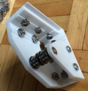
This is made as a two piece assembly in order to keep the part strong along the print layering. The gantry itself will form a box frame which will then be lowered onto the four vertical corner posts of the frame.
Initial testing is indicating that this corner is a snug fit and very strong. The idlers align well with the idlers on the new flat-bar X axis, so everything is coming together nicely for the new design.
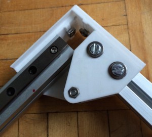
Below is the corner with it’s two extrusions inserted.
by B Cantin | May 27, 2015 | Gemini 3D Printer
As I mentioned in my previous post, I am experimenting with a revised gantry for the Gemini 3D printer.
Here is a test assembly of the new idler ends assembled with the flat aluminum bar support and the 9mm hiwin rail for the X axis mounted.
This design is proving to be adequately stiff for the light weight x-carriage I have been working with on the prototype. Some simple testing shows that it would probably be stiff enough to carry a pair of stepper motors if the design was to use direct drive extruders, however in such a scenario I would probably want a stiffer assembly than the flat bar.
Since the Gemini uses dual bowden extruders, this is a moot point.

This assembly is actually quite simple – there are two printed plastic components, one on each end.
Each end holds three idlers and each idler is composed of two bearings.
The idlers are mounted on M4 bolts which have enough plastic support at their base to handle the tension of the GT2 belts once the gantry is fully assembled.
The lower idlers on the posts that have two idlers are there to prevent the timing belts from rubbing against the idler tower and carry no direct loading. In the initial prototype I observed some rubbing against the plastic support pieces and it occurred to me that the easiest way to solve this problem was to add an extra idler per side.
The double idlers are separated by a small M4 nut. The machining of the bolt head and nut are the perfect size to engage the inner ring of the bearings and not contact the rotating outer assembly and thus eliminate the need for washers.
It would take much more force than this machine will exert to bend the M4 bolts or crack the plastic end pieces.
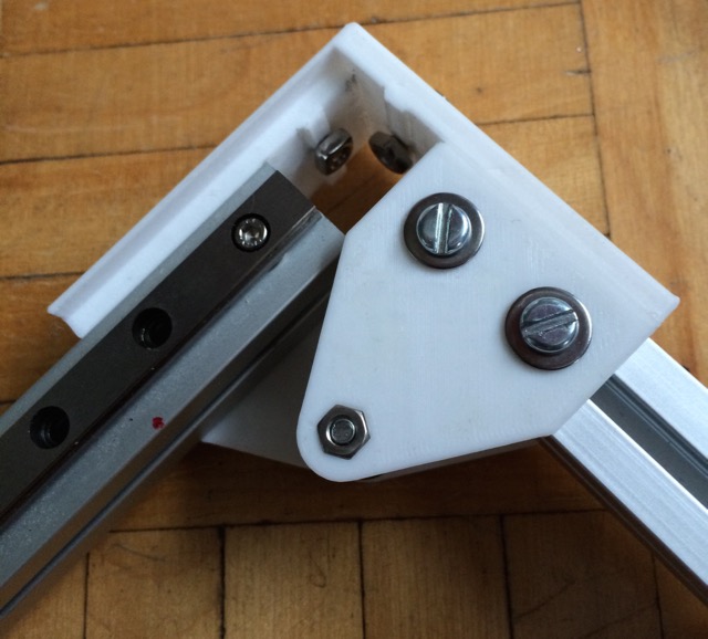
Two M3 bolts on each side sandwich the 9mm rail and the flat bar to the plastic end piece, with an additional three M3 bolts securing the rail to the bar directly which are spaced evenly along it’s length.
This construction ensures that the bar and the rail the are aligned correctly and that they cannot flex independently which provides the necessary stiffness.
Four more M3 bolts on each end connect the X axis to the hiwin carriages on the Y axis with the flat bar sandwiched between the plastic and carriage. This gives additional stiffness to the assembly and ensures proper squared alignment on the Y rails.
by B Cantin | May 26, 2015 | Gemini 3D Printer
The previous prototype of the Gemini 3D printer gantry worked effectively however there are many aspects that I have been working on revising.
Plastic parts in use on the x-end/y-carriage were not designed to be robust in the prototypes – it was assumed that they would be replaced with a better design in the future, so they were made with the most minimal use of plastic to avoid waste on what was expected to be a throw-away part.
While working on what will be a more robust setup I’ve been experimenting with several conceptual changes.
The first major revision involves the belt paths. The motor-end idler pulleys are being removed entirely and the inner dimensions of the belt path will be significantly reduced by this change. This removes several bearings and an extra 90 degree turn from the belt path, shortening the length of GT2 timing belt required and lowering the part count.
The second major revision is to decouple the gantry from the top of the Z axis which will provide more space for the X carriage assembly as well as creating a more directly square frame to constrain the gantry within. I am working on a new design which places the Y axis linear rails underneath the aluminum extrusion instead of on top of it.
A potential pitfall of this change is that it may require an extra metre of aluminum extrusion, or some more drastic re-arrangement of the frame design to accomplish this.
The third major revision – which may be a bit more controversial than the previous two – is to replace the aluminum channel supporting the X axis with a thick length of aluminum flat bar. The reasoning for the channel is that having two different planes on the support will prevent deflection of the X axis over it’s widthwise span.
Testing has indicated that it takes one-thousand grams or more of weight to cause significant deflection of the hardened steel linear channel on it’s own. Bolting it to a length of flat bar increases the amount of weight necessary to cause deflection.
However, the current X carriage design weighs only 200 grams which is not enough to create any significant distortion.
I am still working on this design and might decide to play it safe and use a corner channel ultimately as this will also provide the necessary mounting points for the new design as well as the deflection strength.
Testing is still in progress for this – ultimately the extra reinforcement seems unnecessary if the x-carriage is a fifth of the weight that necessitates it.
The forth revision involves the belt alignment as it relates to the X axis. The goal here is to make the x-end/y-carriage assembly simpler and stronger as well as aligning the belts in such a way as to make clamping them to the X-carriage simpler. This revision puts all four ends of the two belts inline with each other, which is strangely not something I’ve seen elsewhere in a corexy design.
Additional changes to the frame, motor mounts and idlers are in the works as well.
Stay tuned for pictures and/or renderings soon!


Recent Comments